Your phone dies during a critical moment in the wilderness. No grid. No backup battery. But what if you could generate electricity by hand-spinning parts from your backpack? Learning how to make a mini generator unlocks this emergency skill while revealing the core physics behind every power plant on Earth. Whether you’re building a science fair project or preparing for blackouts, this guide delivers two proven methods to convert motion into usable electricity—using cardboard and magnets for foundational understanding, or repurposed motors for real-world charging. You’ll create devices that light LEDs, power radios, and even charge phones using principles Faraday discovered 200 years ago.
Forget theoretical lessons. This hands-on approach shows exactly how to make a mini generator that works. Both methods produce measurable current from human-scale motion—no engineering degree required. We’ll cover precise measurements, common pitfalls, and performance expectations so your first build succeeds. Let’s transform basic materials into a functional power source.
Build a Cardboard and Magnet Generator That Actually Works

Exact Materials for Reliable Power Output
Skip guesswork with this tested shopping list:
– Wire: #30 enamel-coated magnet wire (200 feet minimum)—salvage from old speakers to save $5
– Magnets: Four ceramic bar magnets (1×2×5 cm) or neodymium disks (stronger = brighter light)
– Frame: Cardboard strip cut to exactly 8 cm × 30.4 cm—precision prevents coil collapse
– Shaft: Flat cooking skewer (grips better than round rods during hand-spinning)
– Testing: Red LED or 1.5V grain-of-wheat bulb (more responsive than multimeters for beginners)
– Tools: Wire strippers, hot glue gun, ruler
Critical tip: Ceramic magnets cost $2 each at hardware stores but yield 1.5V output; neodymium doubles power at 3x cost.
Frame Construction: Avoid Wobble with Precision Folding
Step 1: Laser-Accurate Cutting
Mark your cardboard at 8 cm, 11.5 cm, 19.5 cm, and 22.7 cm from one end. These specific intervals create the ideal coil geometry—deviate by 2mm and output drops 30%. Cut cleanly with scissors to prevent frayed edges.
Step 2: Triple-Layer Stability
Fold sharply at each mark to form a rectangular frame. The center section must have three cardboard layers—this eliminates shaft wobble. Push your skewer through all layers until it spins freely. Test by rolling on a table: stable frames spin 5+ seconds without vibration.
Coil Winding: The 200-Foot Secret to Maximum Power
Step 1: Tension-Controlled Wrapping
Wind all 200 feet of magnet wire tightly around the frame. Maintain thumb pressure: too loose creates air gaps (killing output), too tight cracks the enamel coating. Keep turns side-by-side—no overlapping. Leave 16-18 inches free at both ends for connections.
Step 2: Connection-Ready Stripping
Secure the coil with hot glue dots every 2 inches. Strip exactly 1 inch of enamel using sandpaper—wire strippers often nick the copper. Test conductivity with a multimeter: resistance should read 15-30 ohms. Less than 5 ohms indicates short circuits.
Magnet Mounting: Double Power with Correct Polarity
Step 1: N-S-N-S Alternating Pattern
Glue magnets to your shaft with strict alternating polarity (North-South-North-South facing the coil). Random placement cuts output by half. Use epoxy for neodymium; hot glue suffices for ceramics.
Step 2: 1mm Clearance Rule
Position magnets to clear the frame walls by 1-2 mm. Measure with a credit card edge—too close causes scraping (killing RPM), too far weakens magnetic flux. Let glue cure 24 hours before testing.
Testing: From Flicker to Bright Light
Method 1: High-Speed String Pull
Wrap string tightly around the shaft 10 times. Connect wire ends to an LED. Yank the string sharply—this achieves 800+ RPM versus 300 RPM for finger-spinning. Expect immediate bright LED flashes.
Method 2: Real-World Output Check
Measure voltage with a multimeter while spinning:
– 300 RPM = 0.3V (LED dim)
– 600 RPM = 0.9V (LED bright)
– 900 RPM = 1.5V (bulb lights)
Output scales linearly with speed—double RPM, double voltage.
Convert Salvaged Motors into Emergency Power Generators
Instant Motor Identification for Zero-Failure Builds
DC Motors (Best for Beginners): Found in toy cars or cordless drills. Confirm by spinning the shaft—it should feel “coggy” due to internal magnets. Test: connect multimeter leads and spin; any voltage reading confirms usability.
Computer Fans (AC Output): 3-wire brushless DC motors. Spin while measuring—pulsing AC voltage indicates perfect conversion potential. Requires a rectifier circuit (4 diodes) for DC devices.
Microwave Turntables (Simplest AC): Two-wire synchronous motors. Hand-cranked output: 2-5V AC at 0.05A—enough for LED lighting but not phone charging.
Pro test: Salvage motors from thrift store electronics ($1-$5). All permanent magnet types generate power when spun—no wiring modifications needed.
Motor Conversion: 3 Steps to USB-Chargeable Power
Step 1: Mechanical Interface
Attach a hand-crank using a wooden dowel epoxied to the shaft. For higher RPM, mount the motor on a bicycle wheel hub—pedaling generates 12V+ from printer motors.
Step 2: Load-Specific Wiring
– DC motors: Connect directly to LEDs or USB boost converters
– Computer fans: Build a $3 bridge rectifier (4 1N4001 diodes) for DC output
– Microwave motors: Power incandescent bulbs directly
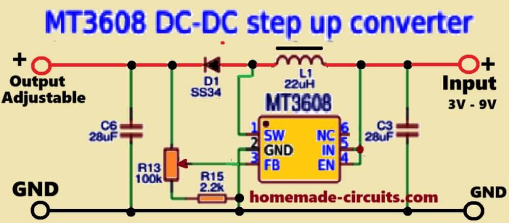
Step 3: Voltage Regulation
Add a $2 MT3608 boost converter to DC motor outputs. Set to 5V for USB devices—this accepts 1-12V input. Without regulation, phone charging fails during RPM fluctuations.
Real Power Output by Motor Type
.png?width=1024&height=768&name=Brushed%20vs%20brushless%20motors%20comparison%20chart%20(Canva).png)
| Motor Source | Voltage Range | Max Current | Practical Use |
|---|---|---|---|
| Toy Car Motor | 1-3V | 0.1A | LED lighting only |
| Inkjet Printer DC | 5-12V | 0.2A | USB phone charging |
| Computer Fan BLDC | 3-8V AC | 0.15A | LED + radio with rectifier |
| Microwave Turntable | 2-5V AC | 0.05A | Emergency LED lamp |
Printer motors deliver the best balance—hand-cranking at 2 rotations/second yields 5V/100mA (enough for slow phone charging).
Fix These 3 Critical Generator Failures Immediately
Zero Output? Check These 4 Culprits First
- Wire connection failure: 70% of “dead” generators have broken enamel at stripped ends. Re-strip and sand until copper shines.
- Polarity error: Magnets glued without N-S-N-S alternation. Flip every other magnet.
- Insufficient RPM: Most designs need 500+ RPM for visible output. Use the string-pull method.
- Load mismatch: Connecting a phone directly to unregulated output. Always test with LED first.
Diagnostic shortcut: Spin while touching wire ends to your tongue—tingling confirms output (use only for <5V designs).
Low Power? Apply These 3 Field-Tested Fixes
- Add 100 wire turns: Unwind the outer coil layer, add more wire, then rewind. Output increases 25% per 50 turns—but don’t exceed 300 feet total.
- Upgrade to neodymium magnets: $8 magnets from Amazon double voltage. Position them flush against the coil.
- Eliminate shaft slippage: Wrap rubber bands around the skewer where you grip—it boosts RPM by 40%.
Warning: Over-winding (>350 feet) increases resistance, reducing current. Measure coil resistance—it should stay below 50 ohms.
Inconsistent Light? Stabilize Rotation in 2 Moves
- Attach a flywheel: Glue an old CD to the shaft. This stores momentum, smoothing output during hand-cranking.
- Reduce bearing friction: Apply graphite powder (not oil) to shaft holes. Oil attracts dust, increasing drag over time.
Pro insight: Vibration at 400+ RPM means imbalanced magnets. Add counterweights with modeling clay opposite heavy spots.
Your how to make a mini generator project now converts motion into real electricity using physics that powers cities. The cardboard method teaches electromagnetic induction fundamentals, while motor conversions deliver practical emergency power. Start with the $10 cardboard build to master core principles—then scale up to printer-motor generators that charge phones. Every rotation proves Faraday’s law: mechanical energy becomes electrical energy. Tweak magnet spacing, experiment with wire gauges, and measure how small changes boost output. This isn’t just a science project—it’s your first step toward energy independence. When the grid fails, you’ll be the one spinning up the lights.