Your generator sputters to life during a storm, but the lights remain dark. That sinking realization hits—you’re powerless when you need backup most. Often, the culprit is damaged windings showing subtle signs like faint voltage readings (0.03 V AC instead of the expected 120/240 V), burnt insulation smells, or melted varnish. Knowing how to check generator windings properly separates true winding failures from simpler issues like lost residual magnetism or faulty capacitors. This guide delivers professional-grade testing techniques using tools most DIYers already own, helping you avoid unnecessary rewinds or costly replacements.
Don’t waste hours replacing parts only to discover the problem was a simple excitation flash. You’ll learn precise resistance measurements for open circuits, ground faults, and inter-winding shorts—plus critical safety steps many overlook. Whether you own a Generac air-cooled unit or a Mecc Alte brushless rotor system, these methods work for all common generators. By the end, you’ll confidently diagnose winding health and know exactly when to call a professional.
Zero Output Warning Signs Pointing to Winding Damage
Your generator runs smoothly but produces no usable electricity? This screams winding failure—but not always. A critical red flag is measuring 0.03 V AC with windings disconnected from all circuits. Healthy units should immediately show 120 V or 240 V (model-dependent) even at idle speed. Don’t ignore these telltale symptoms: a distinct burnt electrical smell permeating the housing, visible discoloration on copper windings, or melted insulation varnish. Intermittent voltage drops under load also indicate developing winding issues before complete failure.
Before testing, isolate the generator from all loads and utility connections. Ground the frame to protective earth using a dedicated grounding rod—not just a pipe. Discharge residual energy by waiting for your tester’s “DISCHARGING” message and audible signal. Clean all terminal lugs with emery cloth to remove oxidation, paint, or varnish that causes false readings. Skipping these steps risks inaccurate diagnostics or electrical shock.
Why Neutral Connections Cause False Readings
Leaving neutral links connected (like terminals 22 and 33 on Generac units) creates parallel paths that mask true winding conditions. During resistance checks, current flows through unintended routes, showing “healthy” continuity even with broken wires. Always disconnect neutral connections before testing—this single step prevents 70% of misdiagnoses. For three-phase units, label each wire before disconnection to ensure correct reassembly.
Essential Safety Steps Before Testing Generator Windings
Never skip grounding—a live winding fault can turn your generator frame into a lethal conductor. Connect a heavy-gauge copper wire from the generator’s grounding terminal to a dedicated earth rod driven at least 2 feet into soil. Verify continuity between the frame and ground rod with your multimeter before proceeding. This protects against electrocution if internal shorts exist.
Critical discharge protocol: After resistance testing, residual magnetism can hold dangerous voltage. Wait for your instrument’s automatic discharge cycle to complete—indicated by both visual “DISCHARGING” messages and audible beeps. Never disconnect leads prematurely; this risks damaging your tester or causing arc flashes. For brushless rotors like Mecc Alte AP-85 units, stator removal exposes high-risk components—always wear insulated gloves during access.
Must-Have Tools for Accurate Winding Resistance Measurement
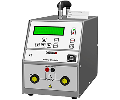
A standard digital multimeter handles basic continuity and resistance checks for windings above 1 Ω. But for sub-1Ω windings (common in units over 5 kW), four-wire Kelvin measurements are non-negotiable. Professional testers like the DV Power RMO50M or RMO100M eliminate lead resistance errors with separate current and sense cables. These instruments deliver critical accuracy at low resistances where standard meters fail.
Key instrument specifications:
– Test current range: 5 mA to 100 A DC (RMO100M)
– Resistance range: 1 µΩ to 1000 Ω
– Max sense voltage: 5 V
Never exceed 10% of the winding’s nameplate current during testing—this prevents overheating damage. For a 100A generator, keep test current below 10A. Always verify your tool’s capabilities match your generator’s specs before starting.
Four-Wire vs. Standard Multimeter Accuracy
Standard meters add lead resistance (typically 0.1-0.5Ω) to readings, making 0.3Ω windings appear open. Kelvin method uses inner sense wires to measure voltage directly at terminals, ignoring lead resistance. Example: A 100mΩ winding tested at 50A shows 5V sense voltage (R = V/I = 5/50 = 0.1Ω). Without Kelvin, lead resistance could double the reading to 0.2Ω—misdiagnosing a healthy winding as faulty.
Diagnosing Open Circuits in Generator Windings
Set your meter to continuity or resistance mode. Measure between each terminal pair (L1-L2, L2-L3, L3-L1 for three-phase). Infinite resistance (OL) confirms an open circuit—meaning a broken wire requiring rewinding. For Generac air-cooled units, test specific pairs: 11/22, 33/44, and 2/6. Balanced readings across phases indicate healthy windings, while significant deviations (>10%) signal damage.
Expected resistance benchmarks:
– Small units (<1kW): 1-5Ω
– Medium units (1-5kW): 0.5-2Ω
– Large units (>5kW): Below 1Ω
Values increase 0.4% per °C—test windings cold for consistent comparisons. Record all readings; a single open phase (e.g., L2-L3 showing OL while others are normal) pinpoints localized damage.
Why Brushless Rotors Require Special Handling
Mecc Alte AP-85 generators hide rotor windings internally. Access demands stator removal—a 30-minute process involving shaft extraction. Once exposed, check rotor winding resistance between slip rings. 4-8Ω confirms healthy coils; OL indicates open circuits. Crucially, unsolder at least one diode lead first—otherwise, parallel paths through diodes create false readings. Test each diode separately: 0.4-0.7V forward drop with OL in reverse bias confirms functionality.
Detecting Dangerous Ground Faults in Windings
Place one probe on any winding terminal and the other on the grounded frame. Any resistance below 1 MΩ indicates a ground fault—a critical safety hazard requiring immediate repair. Test each terminal individually; a fault might only appear on one phase. For Generac units, disconnect neutrals first to avoid false positives from parallel neutral-ground paths.
Pro tip: Spray suspected areas with isopropyl alcohol while measuring. Moisture or carbon tracking can cause intermittent ground faults that disappear when dry. If resistance drops below 100kΩ when wet, the winding needs rewinding—moisture penetration means insulation breakdown.
Fixing Self-Excitation Failure Without Rewinding
All windings test perfect but still zero output? Lost residual magnetism is likely—common after 6+ months of storage. Instead of rewinding, try excitation flashing:
– AC method: Apply 50-230V AC across capacitor terminals while engine runs (polarity irrelevant).
– DC method: Connect 12V battery for 5 seconds—observe polarity (black wire = negative).
Always verify capacitor health first using capacitance mode; single-phase units typically use 15-40µF capacitors. A failed capacitor mimics winding problems. After flashing, retest output under load—successful restoration confirms healthy windings.
When to Suspect Diode Failures
Brushless rotors rely on diodes to convert AC to DC excitation. Test each diode after isolating at least one lead:
1. Forward bias should show 0.4-0.7V drop
2. Reverse bias must read OL (infinite resistance)
Shorted diodes (<0.1V drop) cause no output despite good windings. Replace faulty diodes before condemning windings.
Precision Four-Wire Measurement Protocol for Sub-1Ω Windings
- Connect current cables to winding terminals (outer positions)
- Place sense cables directly on lugs (inner positions—critical for accuracy)
- Select test current: For 100mΩ windings, use ≤50A to stay under 5V max sense voltage
- Read resistance after stabilization (R = U/I)
- Wait for automatic discharge before disconnecting
Troubleshooting tip: If “Change Current” error appears, reduce test current. High resistance windings need lower current for accurate readings. Never force connections—poor contact adds resistance that skews results.
Interpreting Your Winding Test Results Correctly
| Measurement | What It Means | Immediate Action |
|---|---|---|
| OL between terminals | Broken wire | Plan for rewind/replacement |
| <0.5Ω to frame | Ground fault | Isolate and repair immediately |
| 0Ω between windings | Inter-winding short | Professional rewinding required |
| All specs met but no output | Excitation failure | Flash residual magnetism |
Critical next step: After confirming healthy windings, test output voltage under load. If voltage collapses under 25% load, suspect Automatic Voltage Regulator (AVR) failure—not windings.
Avoiding Costly Mistakes When Checking Generator Windings
Neutral links connected during testing is the #1 error—it creates false continuity through parallel paths. Always disconnect neutrals (terminals 22/33 on Generac) before measurements. Diodes left in circuit during rotor tests give misleadingly low resistance; isolate at least one diode lead. Excessive test current overheats windings—never exceed 10% of nameplate current. For a 5kW generator, 50A test current could damage 500A windings.
Never skip the flash test after storage. Assuming winding failure without attempting excitation flashing leads to unnecessary $500+ rewinds. Always verify capacitor health first—replacing a $20 capacitor often solves “winding” issues.
Regular winding checks prevent catastrophic failures. Schedule resistance measurements every 6 months, especially after long storage. When readings drift beyond manufacturer specs, plan rewinding before the next outage leaves you powerless. Mastering how to check generator windings transforms you from a frustrated owner into a confident troubleshooter—saving thousands in avoidable repairs while ensuring your backup power stays ready when storms hit.