That DC generator gathering dust in your garage isn’t obsolete—it’s a hidden AC power source waiting for transformation. Converting a DC generator to produce alternating current isn’t theoretical magic; it’s a practical mechanical modification that replaces the segmented commutator with continuous slip rings. Whether you’re restoring vintage equipment or creating an emergency power solution, this conversion maintains your generator’s original power rating while delivering clean AC output. By following this guide, you’ll transform your DC generator into a reliable AC power source in just a few hours with basic tools.
Replace Commutator with Slip Rings for Continuous Current Flow

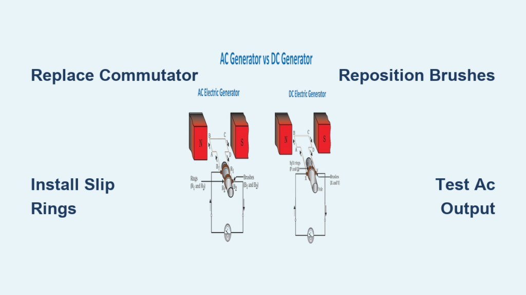
The critical step in converting your DC generator to AC operation involves replacing the segmented commutator with two continuous slip rings. This simple change eliminates the mechanical switching action that converts AC to DC in standard generators, allowing the naturally alternating voltage from the armature windings to pass directly to your external circuit as usable AC power.
Remove Existing Commutator Without Damaging Rotor Shaft
Before touching any components, ensure your generator is completely disconnected from power sources and allow time for any residual energy to dissipate. The commutator removal process requires careful technique to avoid damaging the precision-machined rotor shaft that will support your new slip rings.
Follow this precise removal sequence:
1. Mark brush positions with permanent marker before disassembly—this reference saves hours during reassembly
2. Remove brush assemblies completely and store them in labeled containers to prevent mix-ups
3. Apply controlled heat with a heat gun to soften any retaining compounds (avoid overheating windings)
4. Use proper puller tools to slide the commutator off the shaft—never strike directly with hammers
5. Thoroughly clean the shaft with fine emery cloth to ensure a perfect mounting surface for slip rings
Pro tip: Document each removal step with smartphone photos—these visual references prevent costly mistakes during reassembly and help maintain proper component orientation.
Install Precision-Machined Slip Rings for Reliable Contact
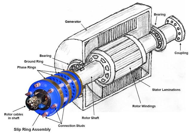
Your slip rings must meet specific dimensional requirements to ensure smooth operation and prevent electrical issues. Unlike the segmented commutator, these continuous rings maintain constant electrical contact with the brushes throughout rotation.
Essential slip ring specifications:
– Material: Brass or copper rings, 3-5mm thick for durability
– Diameter: Match original commutator diameter within ±1mm tolerance
– Spacing: Maintain 2-3mm insulated gap between rings
– Mounting: Use press-fit with keyway or conductive epoxy bonding
Installation process:
– Machine rings to exact shaft diameter for proper interference fit
– Install high-temperature insulation sleeves between rings and shaft
– Apply conductive epoxy sparingly—excess material creates electrical shorts
– Allow full 24-hour cure time before proceeding to brush installation
Critical warning: Verify rings run perfectly true using a dial indicator—any runout exceeding 0.002″ causes brush chatter and unstable voltage output.
Configure Brush Assembly for Continuous AC Output
Your existing carbon brushes remain perfectly functional for AC operation—they simply require repositioning to maintain continuous contact with the slip rings rather than the segmented commutator.
Position Brush Holders at Perfect 180° Alignment
Correct brush placement ensures balanced electrical output and prevents uneven wear on your new slip rings. Unlike DC operation where brushes bridge commutator segments, AC requires continuous contact throughout rotation.
Follow these precise positioning guidelines:
– Maintain 180° separation between brushes for electrical balance
– Center brushes precisely on slip ring width to prevent edge riding
– Set spring tension to 1.5-2.0 PSI for optimal brush pressure
– Verify smooth rotation by hand before final assembly
Warning: Incorrect brush pressure causes either rapid wear (too high) or electrical arcing (too low)—both compromise generator performance.
Verify Electrical Connections Before First Operation
Before energizing your converted generator, conduct thorough electrical verification to prevent damage during initial testing. The connection pattern differs significantly from DC operation despite using the same physical components.
Essential connection checks:
– Positive brush connects to one slip ring
– Negative brush connects to the second slip ring
– Zero cross-connections between rings or to shaft
– Constant resistance throughout full shaft rotation
Quick validation: Rotate shaft by hand while monitoring resistance with a multimeter—values should remain consistent without sudden jumps.
Calculate AC Output Parameters for Proper Application
Understanding your converted generator’s output characteristics prevents equipment damage and ensures compatibility with your intended applications. The conversion doesn’t change the fundamental electrical properties—only how they’re delivered.
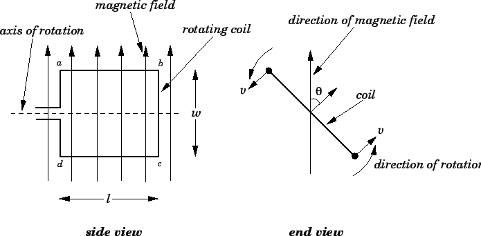
Determine AC Frequency Using RPM and Pole Count
Your generator’s output frequency depends entirely on two factors: rotational speed and magnetic pole configuration. This relationship is critical for powering standard electrical equipment.
Frequency calculation: Hz = (RPM × Number of Poles) ÷ 120
Practical conversion examples:
– 1800 RPM with 4 poles = 60 Hz (standard North American frequency)
– 1500 RPM with 4 poles = 50 Hz (international standard frequency)
– 3600 RPM with 2 poles = 60 Hz (alternative configuration)
Pro tip: Most small generators use 2 or 4 pole configurations—check your original nameplate data for accurate calculations.
Understand Voltage and Power Output Characteristics
The conversion process maintains your generator’s original power capacity while eliminating commutation losses that typically reduce DC generator efficiency by 2-5%.
Power calculation: Watts = Volts × Amps (same as original DC rating)
Example: 12V 50A DC generator = 600W AC output capacity
Critical note: Voltage regulation requires external control since field excitation now solely determines output voltage, independent of frequency.
Test Converted Generator with Progressive Load Sequence
Never apply full load immediately after conversion—follow this systematic testing protocol to identify issues before they cause damage.
Conduct No-Load Testing to Verify Waveform Quality
Initial startup sequence:
1. Hand-rotate generator slowly, listening for mechanical issues
2. Connect oscilloscope to verify pure sine wave generation
3. Measure RMS voltage at rated speed
4. Verify frequency against calculated values
Acceptable results:
– Clean sine wave with minimal distortion
– Stable frequency within ±1 Hz of calculated value
– Voltage stability within ±5% over 5-minute test period
Red flag: Excessive brush sparking, unusual vibration, or voltage instability requires immediate shutdown and troubleshooting.
Implement Gradual Load Testing to Validate Performance
Progressive loading approach:
– 25% load for 10 minutes—monitor temperature and voltage stability
– 50% load for 15 minutes—check brush behavior under stress
– 75% load for 20 minutes—verify cooling adequacy
– 100% load for 30 minutes—full capacity validation
Monitoring checklist:
– Brush temperature should stay below 80°C
– Voltage regulation within ±10% from no-load to full-load
– Frequency stability dependent on prime mover speed control
Expert note: Begin testing with resistive loads (heaters, incandescent lights) for safest initial operation.
Troubleshoot Common Conversion Issues Immediately
Even perfectly executed conversions may develop problems—knowing how to diagnose and fix issues keeps your generator reliable.
Resolve Excessive Brush Sparking with Targeted Solutions
Root causes and fixes:
– Ring contamination: Clean with 600-grit emery cloth
– Incorrect brush pressure: Adjust spring tension to specifications
– Ring runout: Check true with dial indicator—should be <0.002″
– Wrong brush grade: Use same carbon grade as original DC brushes
Quick fix: Light honing with crocus cloth often resolves minor sparking issues without disassembly.
Maintain Your Converted AC Generator for Longevity
Proper maintenance extends generator life and maintains output quality—most procedures match original DC maintenance schedules with minor modifications.
Implement Brush Maintenance Schedule for Continuous Operation
Monthly inspection items:
– Brush wear: Replace when worn to 1/4 original length
– Brush seating: Ensure full contact across ring surface
– Spring condition: Check for fatigue or breakage
– Holder alignment: Verify brushes track ring centers
Cleaning protocol:
– Power off and lockout before any maintenance
– Use compressed air to remove carbon dust—never apply solvents
– Dress brush edges with fine file to prevent chipping
– Vacuum system captures debris during cleaning
Perform Slip Ring Care to Ensure Stable Output
Preventive maintenance:
– Monthly cleaning with lint-free cloth and isopropyl alcohol
– Oxidation removal using 600-grit emery cloth (light pressure only)
– Groove inspection: Replace rings showing deep grooves >0.010″
– Insulation testing: Annual megger test at 500V DC
Critical warning: Black bands on slip rings indicate electrical arcing—requires immediate attention to prevent catastrophic failure.
Convert DC Generator Successfully with Confidence
Transforming your DC generator into reliable AC equipment delivers exceptional value through precise mechanical modification. The conversion process—replacing the commutator with slip rings—creates pure sinusoidal output while eliminating commutation losses. Your converted generator provides emergency AC power, educational demonstrations, or specialized applications at a fraction of new equipment cost.
Key success factors: Precise slip ring installation, proper brush configuration, and methodical testing ensure decades of reliable service. Most conversions complete in 4-8 hours with basic machine shop access and $50-200 in materials.
Ready to power your next project? Start with thorough planning, gather the specified materials, and follow the testing sequence carefully. Your vintage DC generator will soon provide clean, stable AC power for whatever challenge comes next—proving that sometimes, the best power solutions come from smart modifications rather than new purchases.