Your generator starts fine but then the lights flicker, appliances sputter, and voltage readings swing wildly. That’s a classic sign of a generator governor not working properly—the critical component that maintains steady engine speed under changing electrical loads. Without a functioning governor, your power output becomes unstable, threatening connected equipment and creating dangerous operating conditions. This guide delivers precise diagnostic steps and repair procedures to restore proper speed regulation whether you’re dealing with mechanical flyweights or modern electronic controls.
Pinpoint Exact Governor Failure Symptoms
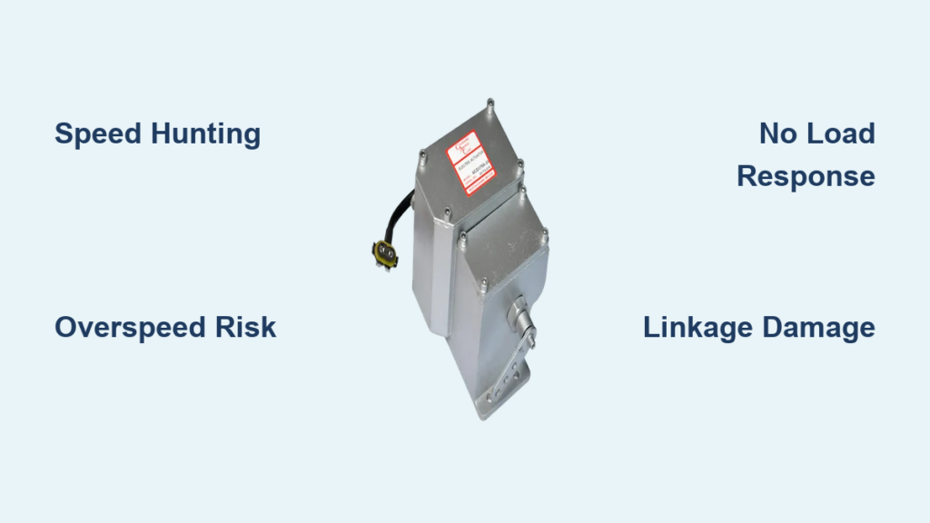
Speed Hunting and Surging
When your generator RPM constantly swings above and below target speed, creating that telltale flickering light pattern, you’re experiencing governor hunting. This unstable oscillation typically shows as frequency meter readings bouncing between 58-62 Hz on 60 Hz systems. The governor overcorrects fuel delivery, then undercorrects in a continuous cycle that prevents stable power output. This symptom often develops within minutes of startup and worsens as engine temperature increases, making it impossible to run sensitive electronics safely.
Complete Speed Loss Under Load
Your generator might start smoothly at no-load but immediately drops 200-300 RPM when you apply electrical demand. Instead of recovering, the engine continues slowing toward stall speed as if starved for fuel. This speed droop condition means the governor mechanism isn’t signaling increased fuel delivery to compensate for load changes. Test this by gradually adding small loads—if RPM decreases proportionally with each added appliance, your governor has lost proper regulation capability and requires immediate attention before complete failure occurs.
Dangerous Overspeed Conditions
The most hazardous governor failure occurs when your engine suddenly races beyond safe operating limits—often 20-30% faster than normal speed. This overspeed condition can destroy your generator in seconds through catastrophic centrifugal force. Listen for a rising whine from the engine that doesn’t stabilize, indicating the governor has lost all speed control. Most generators have emergency shutdown systems that trigger during overspeed, but repeated incidents cause severe mechanical damage to bearings, pistons, and connecting rods.
No Response to Load Changes
A completely failed governor sometimes maintains a fixed engine speed regardless of electrical demand—creating a false sense of stability. Your generator might hold 1800 RPM with no load, but when you add a refrigerator or power tool, the engine speed shouldn’t change at all. This lack of response is actually total governor failure since a properly functioning system should adjust RPM within 3-5 seconds of load application. This condition often precedes complete shutdown as internal components seize.
Immediate Visual Inspection Procedures
Check External Linkages for Damage
Begin with the physical governor-to-fuel connection. Examine control rods, clevis pins, and levers between the governor mechanism and fuel system for visible damage. Gently move the main control rod by hand—it should slide smoothly through its full range without binding or excessive play. Any bent components, disconnected linkages, or worn pivot points immediately explain erratic speed control and often represent the simplest fix in generator governor not working scenarios.
Verify Drive Connection Integrity
Inspect how the governor connects to engine rotation. On mechanical systems, check for sheared drive keys, broken gears, or loose mounting bolts between the engine crankshaft and governor input. Rotate the engine manually (with fuel off) while watching the governor shaft—any lack of rotation means the speed-sensing mechanism has failed. This critical connection must transmit precise engine speed information to the governor for proper regulation.
Inspect for Contamination and Blockages
Look for oil leaks, dirt buildup, or moisture around the governor housing that could interfere with internal mechanisms. Clean linkage joints using compressed air to remove debris without introducing moisture. Never use water or solvents near governor linkages as these can wash away essential lubrication or cause internal corrosion. Pay special attention to pivot points where carbon buildup commonly restricts movement.
Diagnose Mechanical Governor Failures
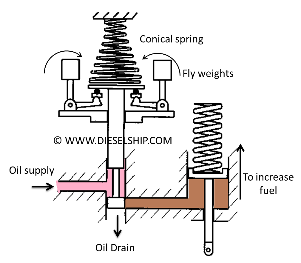
Test Flyweight Assembly Operation
Remove the governor cover to access the flyweight mechanism. Rotate the governor input shaft by hand while observing flyweight movement—they should extend outward smoothly as speed increases. Worn pivot points create sluggish response, while broken flyweights cause complete failure. Replace any components showing visible wear, cracks, or uneven movement to restore proper centrifugal force regulation.
Check Governor Spring Tension
Measure spring length against manufacturer specifications—typically 2-3 inches for standard governors. Gently stretch the spring to test for consistent tension throughout its range. Weak or broken springs cause speed droop under load as they fail to counteract flyweight force. Always replace with exact OEM specifications since spring tension directly determines speed regulation accuracy.
Verify Hydraulic System Health
For hydraulic governors, check oil level through the sight glass—should show 75% full with clean, amber-colored fluid. Release system pressure via the emergency stop before draining a sample to check for metal particles. Contaminated oil causes erratic governor response and must be completely flushed with manufacturer-specified fluid. Never mix oil types as viscosity differences severely impact response characteristics.
Electronic Governor Troubleshooting Steps
Test Sensor Signal Output
Locate the magnetic pickup sensor mounted near the flywheel—typically positioned 0.020″ from the tone ring teeth. Measure AC voltage output with a multimeter while cranking the engine. You should see 2-5 volts AC signal. No signal indicates either sensor failure or incorrect air gap adjustment, both common causes when a generator governor not working with electronic controls.
Verify Control Board Power Supply
Check the electronic governor control unit for proper 12-24V DC supply using a multimeter. Observe diagnostic LED indicators—solid green typically means normal operation while flashing patterns indicate specific fault codes. Consult your service manual for LED flash pattern interpretations as these provide precise diagnostics for electronic governor failures.
Calibrate Electronic Settings
Access the control panel to verify speed settings match your generator specifications—1800 RPM for 60 Hz output, 1500 RPM for 50 Hz systems. Document current settings before making adjustments as improper calibration often mimics hardware failures. Even small deviations (±10 RPM) cause noticeable frequency instability during operation.
Critical Repair Procedures
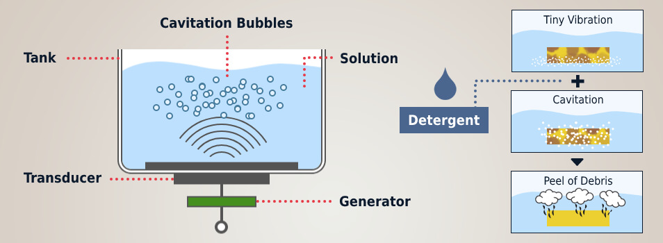
Clean Sticking Fuel Control Valves
Remove the governor-controlled fuel valve and inspect for carbon buildup restricting movement. Ultrasonic cleaning effectively removes deposits without damaging precision components. Test valve travel with a dial indicator—should move full stroke (typically 0.25-0.50 inches) without binding. Sticking valves directly cause governor hunting as fuel delivery doesn’t match load demands.
Service Injection Pump Components
Disassemble the fuel rack mechanism to inspect for worn plungers or seized components. Replace any scored or excessively worn elements as these prevent proper fuel metering. Reset fuel rack positioning to manufacturer baseline before reassembly—critical for matching governor input to actual fuel delivery.
Purge Air from Fuel System
Open all fuel system bleed screws and operate the manual primer until bubble-free fuel flows from each point. Loosen injector lines slightly while cranking to ensure each cylinder receives fuel. Air pockets in the fuel system cause erratic governor response as the system overcorrects for perceived load changes.
Essential Performance Verification
No-Load Frequency Check
Start the generator and allow 5 minutes for stabilization. Use a calibrated frequency meter to verify output—should maintain 60 Hz ±0.25% at no load. Adjust speed setting screw in quarter-turn increments while monitoring frequency until stable readings appear. This baseline check confirms proper governor function before load testing.
Step Load Testing Protocol
Apply electrical loads in 25%, 50%, and 100% increments while monitoring speed recovery. Time the stabilization period—a properly functioning governor should return to rated frequency within 3-5 seconds after each load application. Recovery times longer than 10 seconds indicate governor adjustment or component issues needing correction.
Preventive Maintenance Essentials
Weekly Inspection Checklist
- Visually check all governor linkages for looseness or damage
- Verify oil level in hydraulic governors through sight glass
- Listen for unusual clicking or grinding noises during operation
- Record frequency readings at no-load and full-load conditions
Annual Overhaul Requirements
- Completely replace governor oil and filters per manufacturer schedule
- Measure wear on critical linkage components using micrometers
- Test mechanical overspeed trip mechanism functionality
- Re-calibrate electronic control settings against certified standards
Safety Critical Repair Protocols
Lockout/Tagout Procedures
Always disconnect generator power sources before governor service—both electrical output and starting batteries. Tag all isolation points to prevent accidental startup during repairs. Fuel systems remain pressurized—safely relieve pressure before disassembly to avoid dangerous fuel spray.
Spring Energy Hazard Management
Mechanical governors contain powerful springs under constant tension. Use proper spring compressors during disassembly—not improvised tools that could release violently. Never attempt governor spring adjustments while the engine runs as sudden release can cause serious injury from flying components.
When your generator governor not working symptoms appear, systematic diagnosis prevents wasted time replacing good parts. Start with simple visual checks before progressing to electronic diagnostics, always prioritizing safety during testing. Remember that 80% of governor failures stem from preventable issues like contaminated oil, loose connections, or neglected maintenance—making regular service your most effective protection against unstable power output. For complex electronic failures or internal mechanical damage, consult a qualified technician to avoid compounding problems through improper repair attempts.


