Your generator’s armature has seized after years of service, and you’re facing a critical power outage. When the brush assembly stops spinning or winding damage causes intermittent output, knowing how to remove generator armature from engine becomes essential. This precise procedure prevents costly collateral damage to stator windings or shafts while eliminating electrocution risks from residual capacitor charges.
Skipping safety protocols risks turning a routine repair into a catastrophic failure—magnet wire insulation melts at 300°F, and a single dropped armature can shatter permanent magnets. Follow this sequence to extract your armature safely: isolate all power sources, verify zero voltage, and secure mechanical stability before touching a single bolt. You’ll gain professional techniques for stubborn removals that save hundreds in shop fees while avoiding common DIY mistakes that destroy replacement parts.
Critical Safety Lockouts Before Armature Removal
Electrical Power Isolation That Prevents Electrocution
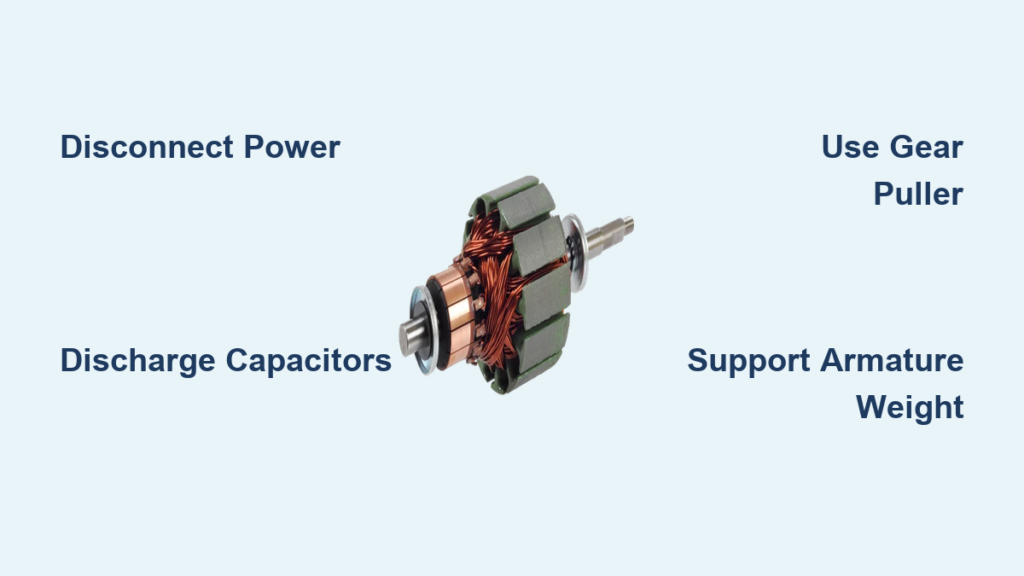
Start by disconnecting the battery negative terminal first, then positive—this breaks the ground path that could turn your wrench into a conductor. Locate cylindrical capacitors near the voltage regulator and discharge them using an insulated screwdriver across terminals for 30 seconds. Never skip multimeter verification: set it to AC/DC voltage and confirm zero volts on every wire. Remove all metal jewelry—your wedding ring becomes a lethal heating element if it bridges live terminals during accidental contact.
Mechanical Stability Setup for Safe Disassembly
Secure the engine on a level surface using wheel chocks or lag bolts through mounting holes. Remove the spark plug wire to eliminate accidental starting risks while working. If tilting the engine for access, drain both fuel and oil completely—gasoline spilled on hot exhaust manifolds creates instant fireballs. Document every wire connection with detailed photos; your memory fails when facing 20 identical black wires under time pressure. Skipping this step causes miswiring that destroys new voltage regulators during reassembly.
Essential Tools for Successful Armature Extraction
Basic Hand Tools You Can’t Skip
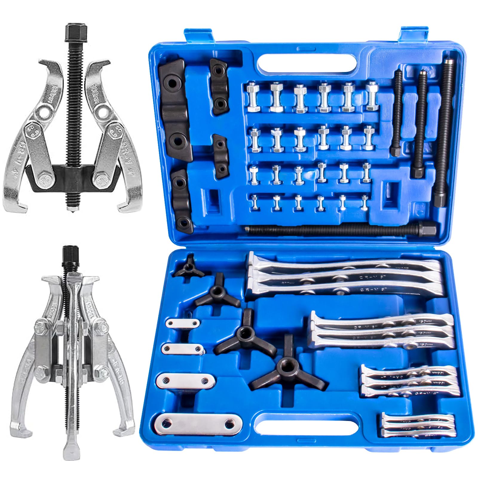
You’ll need a complete socket set covering both metric and SAE sizes—generator manufacturers notoriously mix standards. A 3-jaw gear puller with 4-6 inch reach is non-negotiable for extracting stuck pulleys without mushrooming the shaft. Insulated-handle screwdrivers prevent accidental short circuits, while Allen keys (especially 5mm and 6mm) access hidden rotor bolts inside end bells. Never substitute standard plastic handles—they crack under electrical stress, exposing live conductors.
Specialized Extraction Tools for Stubborn Armatures
For corrosion-seized units, add a bearing separator that applies even pressure behind the armature without crushing windings. An armature puller specific to your generator model grips critical points generic tools miss. Keep a heat gun ready to warm bearing housings to 200-250°F—this thermal expansion breaks rust bonds without damaging magnet wire insulation. A digital caliper verifies shaft dimensions to ensure replacement bearings match within 0.001″ tolerance.
Pre-Removal Diagnostics That Prevent Costly Mistakes

Electrical Health Check Before Disassembly
Test stator windings for shorts to ground: you need greater than 1 megohm resistance. Measure rotor continuity between slip rings—expect 2-10 ohms depending on generator size. Use a megohmmeter at 500V to confirm insulation resistance exceeds 1 megohm; values below indicate failing windings requiring full rewinding. Document brush wear patterns with your phone—uneven erosion signals alignment issues that’ll destroy new brushes immediately after reassembly.
Mechanical Wear Assessment You Must Perform
Mount a dial indicator on the shaft to check runout—maximum 0.002″ total indicator reading is acceptable. Excessive wobble reveals bent shafts or worn bearings. Inspect the keyway for damage; even 0.005″ wear causes pulley slippage during operation. Verify cooling fan clearance and blade integrity—cracked blades become dangerous projectiles at 3600 RPM. Misaligned belts from improper pulley positioning accelerate bearing failure.
Access Preparation Steps for Armature Removal
Housing Disassembly Without Wire Damage
Remove end bell covers using 8mm or 10mm sockets—these hide the armature’s working end and often hide under grease. Take detailed photos of every wire connection before disconnecting the voltage regulator plug and sensing wires. Label wires with numbered tags; these fragile connectors cost $150+ to replace if broken. Remove the brush holder assembly by loosening two retaining screws—the brushes ride directly on slip rings and must clear the armature during extraction.
Drive Component Removal Sequence
Slacken the drive belt tensioner and slide the belt off. Extract the pulley nut (typically 19mm or 21mm torqued to 75-125 ft-lbs) using an impact wrench. If the pulley resists, apply your gear puller—never hammer directly on the shaft. Note the cooling fan’s directional orientation; backward installation causes immediate overheating. Carefully extract the Woodruff key from the shaft keyway with a small pry bar—losing this precision component guarantees pulley slippage during operation.
How to Remove Generator Armature from Engine Safely
Bearing Housing Separation Without Cast Damage
Remove the 4-6 through-bolts securing the bearing housing—clean the area first to reveal hidden fasteners. Tap the housing gently with a soft-faced hammer to break the seal; sharp impacts crack aluminum housings. Always support the armature’s weight during housing removal—dropping an 8-75 lb rotor shatters magnets or bends the shaft. Inspect bearings for contamination that caused the failure before proceeding.
Controlled Armature Extraction Techniques
Install your gear puller with jaws gripping the rear bearing inner race—never pull directly on the rotor. Apply steady pressure using the puller screw; avoid shock loads that bend shafts. For resistance, spray PB Blaster penetrating oil and wait 15 minutes. If still stuck, heat the bearing housing to 200-250°F with a heat gun—aluminum expands faster than steel, breaking corrosion bonds. Maintain gradual pulling force (100-400 lbs) until the armature clears the stator bore.
Troubleshooting Stubborn Armature Removals
Corrosion and Rust Breakthrough Methods
For frozen armatures, spray a 50/50 mix of acetone and automatic transmission fluid—this penetrates deeper than commercial products. Allow 24 hours for severe corrosion before reapplying pressure. Use a bearing separator positioned behind the rotor to prevent cocking during extraction. Never exceed 300°F heating—higher temperatures melt magnet wire insulation, creating hidden shorts that cause failure under load.
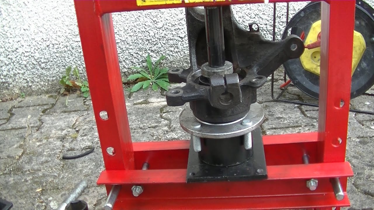
Pressed-Fit Bearing Removal Without Shaft Damage
Use a hydraulic press with minimum 2-ton capacity for pressed-fit bearings. Support the inner race only during pressing—supporting the outer race transfers load through balls, ruining the bearing. Apply slow pressure (500-1000 PSI max) while monitoring movement with a dial indicator. Replace any bearing requiring over 2 tons removal force; the bearing seat is likely damaged and will destroy new bearings quickly.
Post-Removal Inspection Before Reassembly
Rotor Condition Assessment Critical Points
Test rotor windings for opens—you need 2-8 ohms between slip rings. Check slip ring runout with a dial indicator; maximum 0.001″ is acceptable. Measure slip ring diameter—replace if less than 0.250″ material remains. Inspect cooling fan blades for hairline cracks; these propagate rapidly under centrifugal force. Verify shaft straightness using V-blocks—over 0.002″ runout causes destructive vibration.
Bearing Failure Analysis That Prevents Repeat Failures
Check inner/outer races for blue/brown discoloration indicating overheating. Test bearing clearance with feeler gauges—expect 0.001-0.003″ for your size. Listen for grinding during manual rotation; any roughness mandates replacement. Measure bearing dimensions precisely—0.001″ undersized replacements fail within hours from excessive play.
Reassembly Preparation for Long-Term Reliability
Component Cleaning Protocol for Performance
Clean all metal surfaces with brake cleaner—petroleum solvents leave conductive residues. Remove old gasket material with plastic scrapers to avoid scratching sealing surfaces. Polish slip rings with 600-grit sandpaper in circular motions; straight scratches cause brush noise and rapid wear. Blow out ventilation passages with compressed air—blocked cooling causes 80% of premature winding failures.
Replacement Parts Verification Checklist
Always install new bearings—generator-specific part numbers are critical for proper fit. Replace brushes if less than 0.250″ remains; worn brushes damage new slip rings. Verify Woodruff key dimensions match exactly—0.005″ undersized keys cause pulley slippage. Apply thread-locking compound to critical fasteners; vibration loosens bolts, creating catastrophic failures during operation.
When to Call Professionals for Armature Removal
Seek expert help for generators exceeding 50 kW output—these require specialized lifting equipment and precision balancing. Armatures over 100 pounds need engine hoists to prevent injury. If hydraulic press force exceeds 5 tons during bearing removal, the housing is likely damaged beyond DIY repair. Electrical testing showing less than 1 megohm insulation resistance indicates failing windings requiring professional rewinding—typically 60% of a new generator’s cost. Shaft runout over 0.005″ total indicator reading demands machine shop services; DIY straightening usually worsens the damage.
Final Note: Mastering how to remove generator armature from engine transforms intimidating repairs into manageable tasks when you prioritize safety and precision. Document every step with photos, replace consumable parts during reassembly, and test thoroughly before relying on critical power. The difference between a successful repair and expensive damage lies in respecting thermal limits, using correct tools, and knowing when professional expertise becomes essential.