Picture this: your factory floor hums with CNC machines, welders, and conveyor motors—all running simultaneously without a single hiccup in power supply. That seamless operation isn’t magic—it’s the result of a 3-phase generator quietly converting mechanical energy into perfectly timed electrical power. Unlike the flickering lights you might experience with single-phase power at home, three-phase systems deliver continuous, smooth electricity that keeps industrial operations running 24/7. Understanding how a 3 phase generator works reveals why it’s the backbone of modern industry, from data centers protecting critical servers to hospitals powering life-saving equipment.
Three-phase generators produce three separate alternating currents, each offset by 120 electrical degrees. This creates a power delivery system where voltage never drops to zero, making it essential for any operation demanding reliable, high-capacity electricity. When you learn how a 3 phase generator works, you’ll discover why factories, hospitals, and data centers rely on this technology for uninterrupted power.
Mechanical Energy Conversion Process Inside Generators
A 3-phase generator transforms rotational mechanical energy into electrical power through precisely engineered electromagnetic interactions. The process begins with a prime mover—typically a diesel engine, gas turbine, or wind turbine—spinning the generator’s rotor at a constant synchronous speed calculated by the formula: rpm = 120 × frequency ÷ number of poles. For a 60 Hz system with four poles, this means maintaining exactly 1,800 rpm without variation.
Inside the alternator, three identical winding sets sit 120 degrees apart within the stationary stator. As the rotor spins, its magnetic field cuts across these windings, inducing voltage in each phase. The timing creates three separate sine waves that peak at different moments, ensuring continuous power flow. This arrangement delivers approximately 180% more capacity than a single-phase generator of identical physical size.
The rotor itself comes in two main varieties: wound-field rotors using electromagnets powered by an exciter, or permanent magnet rotors utilizing rare-earth magnets. Wound-field systems offer better control over output voltage through field current adjustment, while permanent magnet designs eliminate the need for slip rings and brushes, reducing maintenance requirements. When you examine how a 3 phase generator works at this fundamental level, the elegant simplicity of electromagnetic induction becomes apparent.
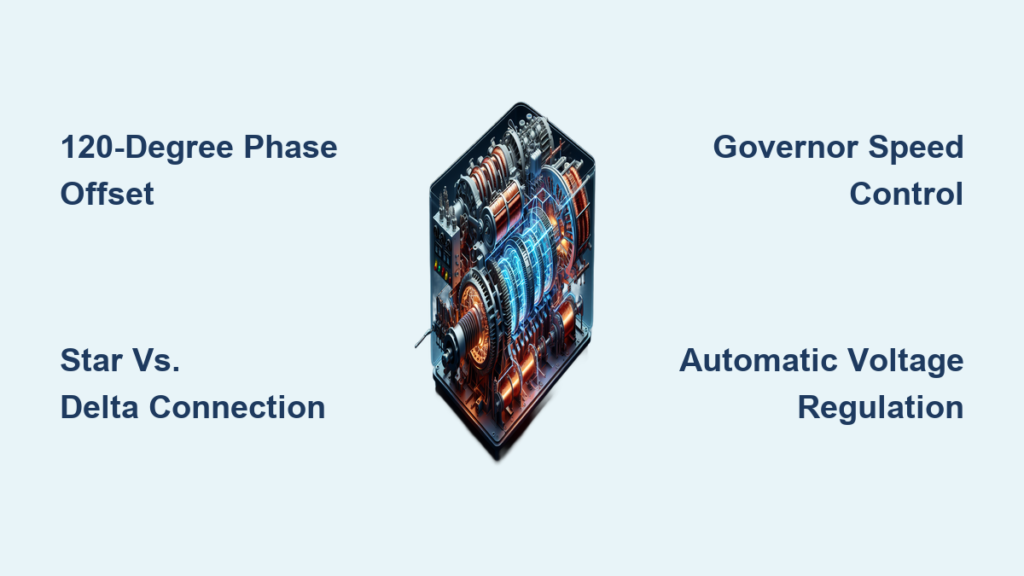
Why 120-Degree Phase Separation Matters
The 120-degree separation between phases isn’t arbitrary—it’s the mathematical sweet spot for balanced power delivery. For phase A (reference), the voltage relationships follow precise patterns: VA = Vm sin(ωt), VB = Vm sin(ωt – 120°), and VC = Vm sin(ωt – 240°). This creates line-to-line voltages that are √3 times higher than phase voltages—explaining why 415V three-phase systems use 240V phase-to-neutral connections.
This specific angular displacement ensures the algebraic sum of the three instantaneous voltages is never zero, meaning power delivery remains continuous. Unlike single-phase systems where power drops to zero 100 times per second (at 50 Hz), three-phase systems provide steady torque for motors and eliminate the flicker that can damage sensitive electronics. When you understand how a 3 phase generator works with this phase relationship, you appreciate why industrial facilities demand this technology.
Star vs. Delta Stator Configurations Compared
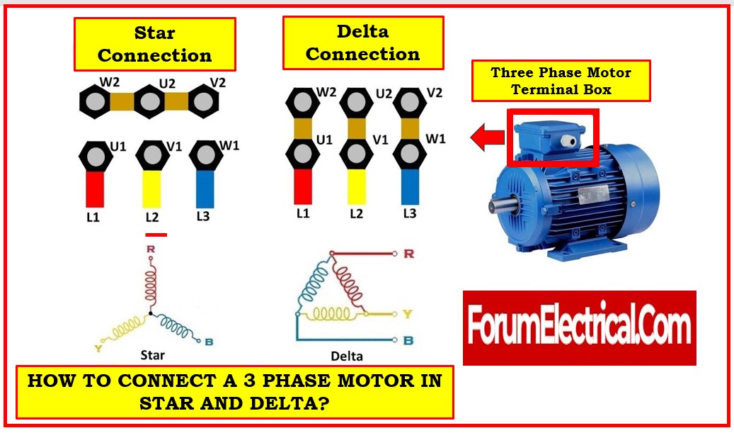
Star (Wye) Connection Advantages
Star connections bring one end of each winding together at a neutral point, creating a four-wire system ideal for mixed single and three-phase loads. This configuration provides two voltage levels from the same generator—phase-to-neutral and phase-to-phase—which proves invaluable in commercial buildings where both types of equipment coexist. The neutral wire also provides a return path for unbalanced currents, preventing voltage fluctuations when loads change.
Most industrial facilities prefer star connections because they allow easier integration of single-phase equipment without additional transformers. When troubleshooting how a 3 phase generator works in star configuration, technicians monitor neutral current (should be near zero in balanced systems) as an early indicator of load imbalances that could damage equipment.
Delta Connection Performance Characteristics
Delta connections form a closed loop between windings, resulting in a three-wire system that handles balanced loads efficiently. Without a neutral point, delta configurations don’t support single-phase loads directly, but they offer higher reliability in harsh industrial environments where neutral faults could cause system failures. The absence of a neutral conductor also reduces installation costs for purely three-phase applications.
Delta systems maintain voltage stability better under heavy transient loads because the closed-loop design allows current to circulate between phases during imbalances. When analyzing how a 3 phase generator works with delta windings, engineers note the system’s superior tolerance to single-phase faults—though complete failure of one winding will disable the entire generator.
Critical Control Systems for Stable Operation
Governor Response to Load Changes
Maintaining exact synchronous speed proves critical for stable frequency output. Modern generators use sophisticated governors to maintain engine speed within ±0.25% regardless of load changes. When a large motor starts or production lines activate, the governor immediately increases fuel delivery to prevent frequency droop. This precision matters because even small frequency deviations can damage sensitive electronic equipment or cause motors to run at incorrect speeds.
Without proper governor response, voltage fluctuations would cause lights to dim and motors to slow during high-demand periods. When you observe how a 3 phase generator works under varying loads, the governor’s split-second adjustments demonstrate why industrial facilities prioritize this component during maintenance.
Automatic Voltage Regulation Technology
Automatic voltage regulators (AVRs) maintain output within ±1% of nominal voltage from no-load to full-load conditions. These solid-state devices continuously monitor output voltage and adjust the rotor’s field current to compensate for changes in load or engine speed. Advanced AVRs incorporate power factor correction capabilities, optimizing generator efficiency by managing reactive power flow.
When troubleshooting how a 3 phase generator works with unstable voltage output, technicians typically check the AVR first. Common issues include dirty sensing circuits, failing capacitors, or worn brushes in wound-field systems. Properly functioning AVRs ensure motors start smoothly and electronic equipment operates within specification.
Industrial Applications and Sizing Requirements
Matching Generator Capacity to Facility Needs
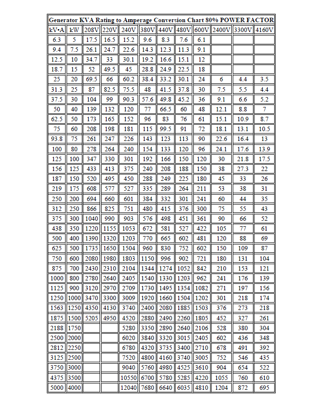
Industrial facilities typically require 30-1,100 kVA generators for continuous operation with N+1 redundancy. Data centers use 250-2,000 kVA units meeting Tier III/IV standards, while hospitals mandate 100-1,000 kVA systems capable of 10-second start times per NFPA 110. The key to proper sizing lies in understanding both continuous and surge requirements.
Quick Sizing Formula: Motor loads need 1 kVA per 0.8 kW motor rating at 0.8 power factor, plus 20% spare capacity for starting surges. A 50 hp motor (37.3 kW) requires approximately 47 kVA generator capacity with surge allowance. When determining how a 3 phase generator works for your specific application, always calculate the worst-case startup scenario where multiple large motors engage simultaneously.
Permanent Magnet Generators in Renewable Energy
Modern wind turbines increasingly employ permanent magnet synchronous generators (PMSG) with rare-earth magnets on the rotor. These systems eliminate exciters and brushes, reducing maintenance while achieving 96-97% efficiency. Full-scale power converters enable variable speed operation while maintaining constant frequency output to the grid.
The rise of PMSG technology demonstrates how a 3 phase generator works in renewable applications where reliability and minimal maintenance prove critical. With no slip rings to wear out and higher efficiency across variable wind speeds, these generators have become standard in new wind farm installations.
Essential Maintenance Practices for Longevity
Preventing Wet-Stacking in Diesel Units
Load bank testing at 80% capacity every 150-250 hours prevents wet-stacking in diesel units by burning off accumulated carbon deposits. This critical procedure ensures engines operate at proper temperature, preventing unburned fuel from contaminating oil and exhaust systems. Many facility managers discover how a 3 phase generator works differently under full load compared to partial load operation during these tests.
Without regular load banking, diesel generators can develop glazed cylinder walls and injector coking, leading to costly repairs and reduced reliability during actual power outages. The maintenance schedule must include these tests to verify the generator performs as expected when needed most.
Weekly Checks That Prevent Catastrophic Failures
Simple weekly checks prevent most generator failures before they occur. Auto-start tests (15 minutes minimum), battery charger verification, and fuel level monitoring catch 80% of potential problems early. Battery voltage below 12.6V indicates sulfation that could prevent starting during an outage.
When facility technicians understand how a 3 phase generator works at the component level, they recognize warning signs like unusual noises, exhaust color changes, or voltage fluctuations that indicate developing problems. Consistent maintenance extends generator life from the typical 15-20 years to 25+ years in industrial settings.
Mastering how a 3 phase generator works provides facility managers with critical knowledge for maintaining reliable power infrastructure. The continuous power delivery, superior efficiency, and built-in redundancy of three-phase systems make them indispensable for any operation where downtime carries significant costs. Whether you’re responsible for a manufacturing plant, data center, or hospital, understanding these principles helps ensure you select, install, and maintain generators that deliver decades of dependable service. By implementing proper sizing, regular maintenance, and appropriate configurations, you can maximize the performance and longevity of your three-phase power systems while avoiding costly downtime.