You’re staring at flickering lights as a storm rages outside. When the power dies, your neighbors panic about spoiled food and frozen pipes—but you flip a few switches and restore essential circuits using your portable generator. The secret? A properly installed generator interlock. This mechanical safety device prevents deadly backfeeding into utility lines while letting you power critical home circuits legally and affordably. Unlike automatic transfer switches costing thousands, a generator interlock kit installs in one afternoon for under $450, making it the smart DIY solution for outage resilience.
This guide delivers the exact steps to install your interlock safely and correctly—no guesswork, no dangerous shortcuts. You’ll learn panel-specific compatibility checks, wiring protocols that pass electrical inspections, and the precise outage operation sequence that protects lineworkers. Most importantly, you’ll avoid the fatal mistakes DIYers make when connecting generators to home panels. Let’s transform your electrical panel into a safe backup power hub before the next outage hits.
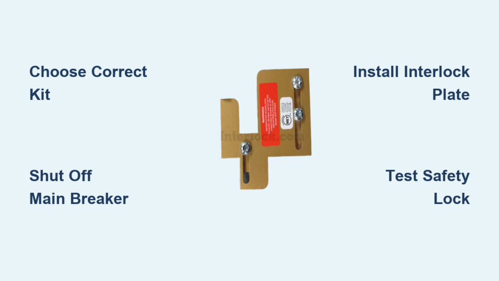
Choose Correct Interlock Kit

Your interlock must match your panel’s exact manufacturer and model—Square D kits won’t fit Eaton panels, and mismatched kits cause dangerous gaps. Before ordering, verify three critical details visible on your panel’s dead-front label: the panel brand (Siemens, GE, etc.), model number, and main breaker amperage (100A, 200A). Also confirm whether your panel accepts tandem breakers if you lack spare slots.
Pro tip: Snap a photo of your panel’s label and breaker layout. Email it to the kit manufacturer’s technical support—they’ll confirm compatibility within hours. Never assume compatibility based on panel age or visual similarity. Using a non-UL-listed kit violates NEC 702.5(B) and creates immediate electrocution risks during outages.
Essential Safety Steps

Working inside a live electrical panel demands zero tolerance for error. Before touching a single screw, complete these non-negotiable steps: First, shut OFF your main breaker—the large topmost switch. Then, use a non-contact voltage tester on the main lugs to confirm zero voltage. Finally, apply a physical lockout tag to prevent accidental re-energization while you work.
Critical warning: If your tester beeps near the bus bars, stop immediately and call an electrician. Never stand on concrete floors or use metal ladders during installation—fiberglass ladders and insulated tools are mandatory. This project isn’t worth your life; if you feel uncertain at any step, halt and seek professional help.
Required Tools and Materials
Gather these items before starting to avoid mid-project delays:
Tools:
– Insulated Phillips/flathead screwdrivers
– Nut driver set (for breaker mounting screws)
– Non-contact voltage tester and multimeter
– Wire strippers and cable cutters
– Drill with 1/2″ masonry bit (for inlet box mounting)
Materials:
– UL-listed interlock kit for your specific panel
– 30A double-pole breaker matching panel brand
– NEMA L14-30 outdoor-rated inlet box
– 10/4 SOOW generator cable (length = panel to generator distance)
– Conduit fittings and anti-short bushings
Never substitute: Hardware store knockoffs lack UL certification and won’t pass inspections.
Prepare Your Electrical Panel
Free Up Breaker Space
Most panels require one full slot for the generator breaker. If all slots are occupied:
- Identify four single-pole 20A breakers powering non-essential circuits (like guest bathrooms or spare bedrooms)
- Replace them with two tandem breakers (each handles two circuits in one slot)
- This frees one full slot for your generator breaker
Critical: Verify tandem compatibility in your panel’s labeling—pre-1990 panels often prohibit them. Overloading bus stabs by adding tandem breakers risks fire.
Remove Panel Cover
Unscrew dead-front cover screws in a crisscross pattern to prevent warping. Store screws in a magnetic tray. Lift the cover straight out while checking for snagged wires—never force it. Exposed bus bars remain lethal even with the main breaker off if utility power is live.
Install Interlock Mechanism
The metal interlock plate physically blocks simultaneous main/generator breaker activation—its core safety function. Position it between the main and generator breaker slots, ensuring smooth sliding motion. Secure with provided screws without overtightening, which causes binding.
Test before wiring: With main breaker ON, the generator breaker must be physically blocked from moving to ON position. Flip main OFF—generator breaker should slide freely into place. If resistance occurs, loosen screws slightly and retest. Binding indicates misalignment that could fail during an outage.
Wire Generator Inlet Box
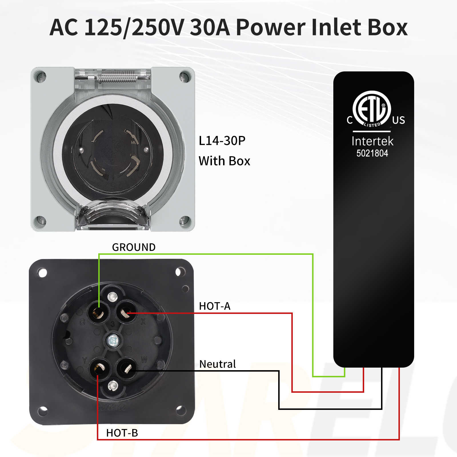
Mount Weatherproof Inlet
Install the NEMA L14-30 inlet box on an exterior wall within 25 feet of your panel, positioned at least 18 inches above ground level. Choose a location sheltered from rain and away from doors/windows where generator exhaust might enter.
Pro tip: Place it near your typical generator staging area—avoiding long cable runs reduces voltage drop. Seal conduit entries with silicone caulk to prevent moisture intrusion.
Route Generator Cable
Run 10/4 SOOW cable through EMT conduit from inlet to panel, using these connections:
– Black wire → generator breaker pole 1
– Red wire → generator breaker pole 2
– White wire → isolated neutral bus bar
– Green wire → equipment grounding bar
Critical: Install anti-short bushings where cable enters metal conduit to prevent insulation damage. Never drape cables over sharp panel edges.
Complete Electrical Connections
Snap the 30A double-pole breaker into the freed slot, ensuring its handle engages the interlock plate. Strip wires to 3/8-inch exposure and torque connections to 20–25 lb-in using a calibrated screwdriver—under-torqued lugs cause arcing, over-torqued ones crack terminals.
Visual cue: Wires should neatly route away from live bus bars without tension. Double-check neutral/ground separation—bonded-neutral generators create shock hazards when connected to home panels.
Test System Function
Before closing the panel, validate safety interlocks:
1. With main breaker ON, attempt to switch generator breaker ON—it must be physically blocked
2. Turn main OFF—generator breaker should slide freely into ON position
3. Simulate outage: Connect generator cord and verify only selected circuits power up
Never skip testing: Faulty interlock movement could allow simultaneous main/generator activation, risking electrocution.
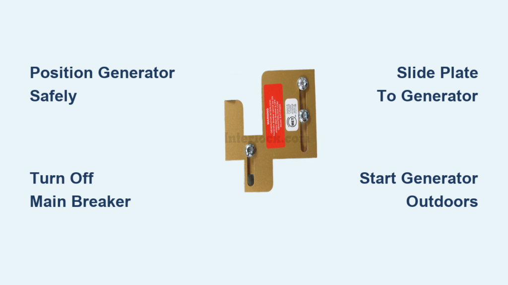
Power Outage Operation Sequence
During actual outages, follow this exact sequence to prevent overload and backfeed:
- Turn OFF all branch breakers (fridge, furnace, etc.)
- Flip main breaker to OFF position
- Slide generator breaker to ON (interlock now blocks main)
- Start generator and let run 2–3 minutes to stabilize
- Turn ON essential circuits one by one, staying under 24A (80% of 30A breaker)
Shutdown sequence: Reverse steps—turn OFF branch breakers first, then generator breaker, then main. Never reconnect to utility power while generator runs.
Common Installation Mistakes
Fatal errors to avoid:
– Using male-to-male “suicide cords” instead of proper inlet boxes
– Connecting generator directly to main lugs (bypasses all safety)
– Drilling panel covers for incompatible interlock kits
– Overloading circuits beyond 80% breaker capacity
Neutral bonding trap: Home panels require floating-neutral generators. Bonded-neutral generators (common on cheap models) create parallel neutral paths causing shocks—verify your generator’s neutral configuration before installation.
Cost and Timeline
DIY investment:
– Interlock kit: $50–$150
– Breaker and inlet: $50–$150
– Wire/conduit: $50–$150
– Total: $150–$450
Time required: 2–4 hours for experienced DIYers; first-timers should budget 4–6 hours. Professional installation averages $500–$1,500 including permits—worth considering if your panel is older than 1980 or lacks tandem compatibility.
Code Compliance Checklist
Before using your system:
– [ ] Interlock kit bears UL listing for your exact panel model
– [ ] Local electrical permit obtained (required in most jurisdictions)
– [ ] Installation inspected by AHJ (Authority Having Jurisdiction)
– [ ] Permanent label installed showing generator breaker location
– [ ] Load calculation performed matching generator wattage
Critical: Even flawless DIY work needs professional inspection. That $200 fee prevents insurance denial after an incident.
Maintenance Requirements
Ensure decades of reliable operation with these annual checks:
– Inspect interlock plate for cracks or corrosion
– Verify smooth sliding motion with main/generator breakers
– Retorque all connections to manufacturer specs
– Exercise generator with 15-minute unloaded run
Pro tip: During monthly generator tests, confirm interlock movement hasn’t stiffened due to vibration. Replace bent plates immediately—they’re safety-critical components.
A correctly installed generator interlock delivers peace of mind when storms strike, keeping your family safe without breaking the bank. By following these precise steps, you’ve created a code-compliant system that protects lineworkers while powering essentials. Now label your critical circuits inside the panel for faster outage responses, and consider adding a whole-house surge protector during your next panel opening. When the next blackout hits, you’ll be the calm neighbor sharing hot coffee while others hunt for gas stations.
Final note: If your generator lacks a floating neutral, consult an electrician before connecting—it’s cheaper than rewiring after an incident. Always prioritize safety over speed; your life depends on it.