Your Generac generator fires right up during an outage but delivers zero electricity to your home. You hear the engine running normally, yet lights stay dark and appliances remain dead. This “ghost generator” scenario affects thousands of homeowners annually—leaving families stranded despite having invested in backup power. The critical detail? When your Generac generator not producing power while running smoothly, the fault almost always lies in the electrical generation system, not the engine. Most cases trace to one of three culprits: rotor excitation failures, stator winding damage, or control wiring errors. By following this systematic approach, you’ll pinpoint the exact failure point and avoid costly service calls.
Why Your Generac Runs But Delivers Zero Power
When your Generac generator not producing power despite normal engine operation, the symptom profile tells a specific story. The transfer switch stubbornly remains in utility position, no warning codes illuminate, and the unit runs indefinitely without self-shutdown. Crucially, you’ll measure 0V AC at three critical locations: the line side of the main circuit breaker, transfer switch load lugs, and generator harness wires 11 & 44. This eliminates fuel, spark plug, or oil pressure issues—your problem is purely electrical generation.
Before grabbing tools, complete these 60-second checks that resolve 30% of cases:
– Verify fuel level exceeds ¼ tank and valves are fully open
– Confirm emergency stop switch is disengaged (pulled out)
– Cycle the main circuit breaker OFF→ON to reset internal contacts
– Test battery voltage (must read ≥12.4V with engine off)
– Inspect transfer switch fuses for visible damage
If all pass yet voltage remains zero, prepare for electrical testing. Critical warning: Always disconnect the battery negative terminal and lock out utility power before proceeding—live 240V circuits pose lethal risks.
Testing Rotor Excitation Circuit Failures
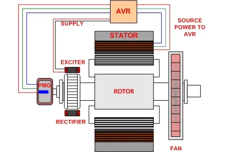
The rotor creates the magnetic field essential for power generation. A shorted or open rotor circuit is the #1 cause of zero output. Here’s how to diagnose it:
Perform the Fixed-Excitation Test (10-Minute Diagnosis)
- Disconnect the controller plug completely
- Apply 12V DC from battery positive to wire #4 (negative to frame)
- Measure AC voltage across stator wires 11 & 44 while cranking
– ~90V AC reading: Stator and rotor are functional—blame lies with controller or regulator
– 0V AC: Confirms rotor or stator failure (proceed to resistance testing)
Check Critical Resistance Values
With brushes lifted from slip rings, measure:
– Controller pins 0→4: Should read 15-30Ω (a reading of 1.025Ω confirms a deadly short circuit)
– Slip-ring-to-slip-ring: Normal range 10.25-11.92Ω
– Slip-ring-to-shaft: Must show ∞ (infinite resistance)—any continuity indicates a ground fault
Pro Tip: Melted brushes or blackened slip rings visible through the inspection port often explain low resistance readings. Replace carbon brushes immediately if worn below 50% thickness.
Diagnosing Stator Winding Failures

The stator contains the actual power-generating coils. Burnt windings from miswiring are irreversible—catch them early with this test sequence:
Complete Phase-to-Phase Resistance Checks
- Disconnect ALL stator leads from main breaker and neutral bar
- Measure between:
– Wires 11↔22: Should read 0.039-0.042Ω (higher = broken winding)
– Wires 33↔44: Same normal range applies
– Wires 11↔44: Must show no continuity (continuity = phase-to-phase short)
Detect Ground Faults in 60 Seconds
Test any stator wire (11,22,33,44,N) to generator frame:
– Continuity present: Confirms stator ground fault (replace stator assembly)
– Burnt insulation smell: Immediate indicator of 240V utility miswiring damage
Critical Insight: Never substitute ground for neutral—this installation error instantly burns stators during first power-up. Smell for acrid odors before testing.
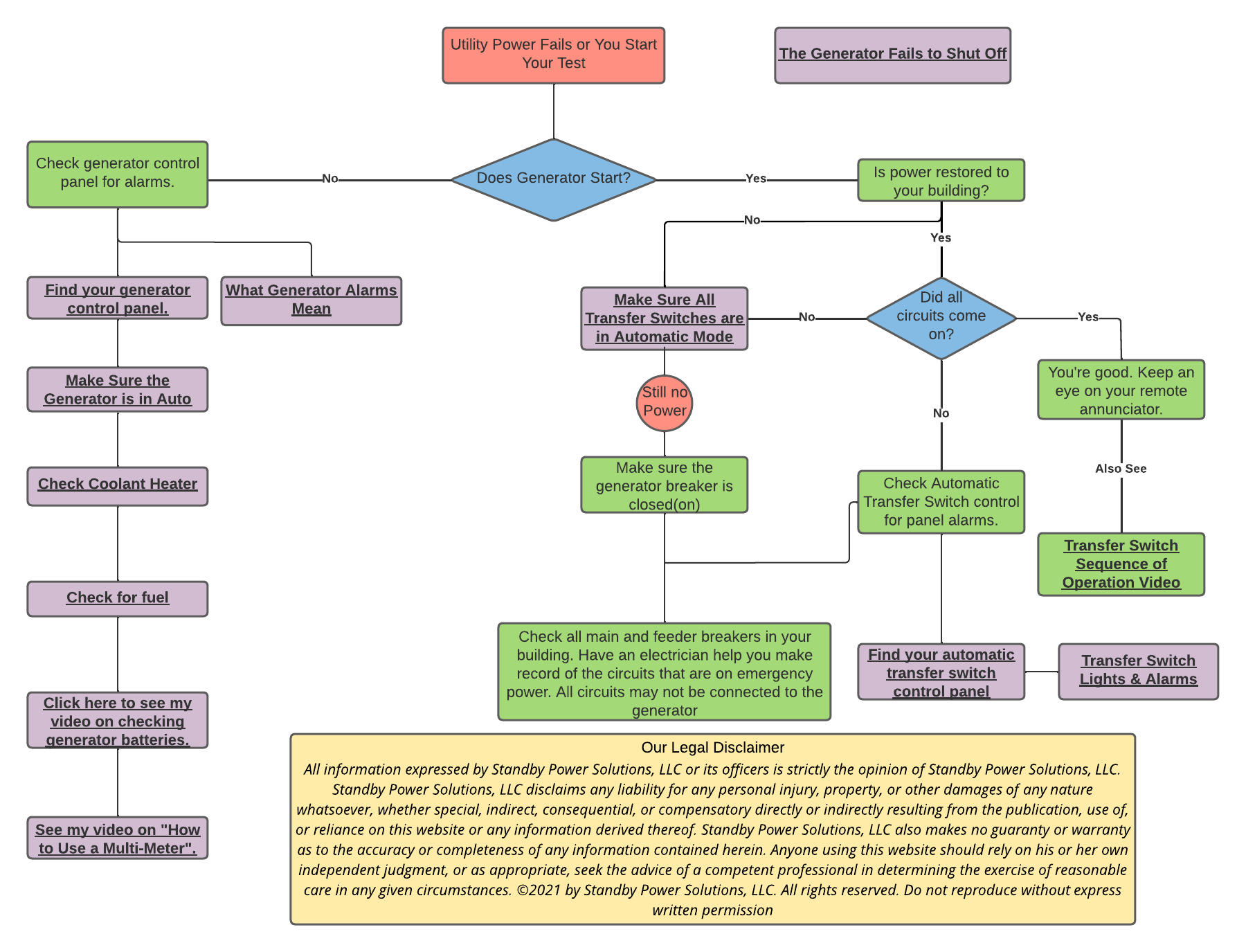
Fixing Control Wiring and Transfer Switch Failures
Faulty signals between controller and transfer switch cause 25% of “no output” cases. Focus on these high-impact checks:
Verify Wire #23 Transfer Signal
This single wire energizes the transfer switch coil:
– Check for continuity from controller pin 23 to SACM module coil
– Confirm 240V AC present on sense wires N1/N2 when utility power is live
– Inspect for scorched SACM modules or unplugged connectors in transfer switch
Identify Controller Damage Clues
Look for these red flags on Evolution/Nexus boards:
– Burnt traces near DC terminals (indicates 120/240V AC miswiring)
– Electrical odor from controller housing
– Use of standard 12/2 Romex for control wiring (requires low-voltage cable)
Warning: Reversing DC lines 194, 0, 4, or 23 instantly destroys controllers. Always verify polarity before reconnection.
Follow This 8-Step Diagnostic Workflow for Guaranteed Results
Skip random part swapping—this sequence isolates faults efficiently:
- Safety Lockout: Stop engine, disconnect battery negative, discharge capacitors (wait 5 min)
- Control Power Check: Verify ≥12.4V at controller input terminals
- Rotor Circuit Test: Perform fixed-excitation test and resistance measurements
- Stator Integrity Scan: Complete phase-to-phase and ground fault tests
- Brush & Slip Ring Inspection: Replace brushes if <50% thickness remains
- Transfer Switch Verification: Confirm 240V on N1/N2 and wire #23 continuity
- Wiring Audit: Check for improper gas line routing through electrical compartments
- Document & Repair: Photograph findings before replacing parts
Time Saver: Record all resistance readings—comparing to spec values (0.039-0.042Ω for stator phases, 15-30Ω for rotor) eliminates guesswork.
Top 5 Installation Errors That Cause Power Loss
These preventable wiring mistakes trigger most catastrophic failures:
| Installation Mistake | Immediate Consequence | How to Fix |
|---|---|---|
| Using ground as neutral conductor | No voltage sensing, stator burnout | Install proper neutral wire per NEC |
| 12/2 Romex for control circuits | 120/240V on DC lines → controller meltdown | Replace with 18-4 low-voltage cable |
| Missing wire #23 connection | Transfer switch never activates | Reconnect to SACM coil terminal |
| Flexible gas line through cabinet | Chafing → gas leak → safety shutdown | Reroute per Generac manual clearance specs |
| Loose lugs on main breaker | Overheating → voltage drop → burnout | Torque to 250 in-lbs (UL489 requirement) |
Replacement Parts Guide for Critical Components
Match your test results to exact part numbers:
| Failure Symptom | Correct Part | Installation Tip |
|---|---|---|
| Rotor resistance 1.025Ω | Rotor Assembly #0G8449 (22kW) | Lubricate slip rings with dielectric grease |
| Stator ground fault | Stator Assembly #0G8450 | Megger test new unit before installation |
| Controller won’t excite | Evolution Controller #0H6680D | Update firmware after replacement |
| Transfer switch stuck | SACM Module RTSN 100-200A | Verify 240V coil operation before mounting |
Critical Note: Always replace carbon brushes (Part #0E9031) when servicing rotors—worn brushes accelerate slip ring damage.
Preventing Future Power Failures With Smart Maintenance
Avoid repeat failures with this proactive schedule:
Monthly:
– Run generator under load for 20 minutes
– Record voltage (should be 120/240V ±3%) and frequency (60Hz ±0.5Hz)
Quarterly:
– Torque all electrical connections to spec
– Measure brush wear (replace at 50% thickness)
– Clean slip rings with 400-grit emery cloth
Annually:
– Megger stator insulation (must read ≥1MΩ to ground)
– Replace air filter and spark plugs
– Schedule professional control calibration
After Every Outage:
– Confirm transfer switch returns to utility position
– Check for new warning codes in controller display
– Document any performance anomalies immediately
When to Call Generac Professionals and Get Support
Contact certified technicians if you encounter:
– Burnt stator smell or visible coil damage
– Controller boards with melted components
– Gas line routing through electrical compartments
– Any wiring violating NEC Article 702
Factory Direct Support: Reach Generac’s technical team at 1-800-822-5436 (U.S.) or use their dealer locator for certified field service. Provide your unit’s serial number—they’ll pull exact schematics for your model.
Your Generac generator not producing power almost always traces to a single electrical fault—not engine failure. By methodically testing rotor excitation, stator windings, and control signals, you’ll restore backup power faster than waiting for a service truck. Remember: Document every resistance reading, never skip safety lockouts, and replace related components (like brushes when servicing rotors). For persistent issues, Generac’s factory support team has diagnostic charts specific to your model number—don’t hesitate to call when high-voltage circuits or gas lines are involved. With this systematic approach, you’ll transform from powerless homeowner to confident generator troubleshooter.


