
Your Generac generator fires up perfectly during its weekly test, yet when the lights go out, your house stays dark. The engine hums steadily, fuel gauge shows adequate levels, but not a single appliance powers on. This exact scenario leaves thousands of homeowners stranded annually despite having invested in backup power protection. The critical clue? Your Generac generator runs but no electricity reaches your home—a solvable problem in 80% of cases with systematic troubleshooting. You’ll discover why your generator produces zero voltage at the outlets despite normal operation and how to pinpoint whether the issue lies inside the generator or in the power transfer path.
This guide cuts through guesswork with field-tested diagnostic sequences used by certified technicians. We’ll walk you from the simplest breaker check to advanced component testing, helping you distinguish between zero voltage production (internal generator failure) and power path blockage (transfer switch or wiring issues). Most fixes require only a multimeter and basic tools, saving you $300+ service calls while restoring power within an hour.
Verify Your Generator Breaker Position First
Before touching internal components, rule out the most overlooked culprit: a tripped main line circuit breaker (MLCB) inside your generator enclosure. Storm surges or voltage spikes during exercise cycles can silently trip this large breaker without triggering alarms.
Critical inspection steps:
– Locate the MLCB near the control panel (labeled “Generator” or “Main”)
– Confirm the toggle is fully engaged in the UP position—partial trips show no visual indicator
– Check for red trip flags hidden behind the breaker handle
– Firmly reset by moving to OFF then back to ON with decisive pressure
Immediate voltage verification:
1. Start your generator manually
2. Set multimeter to AC volts (300V range)
3. Test between L1 and L2 terminals inside the generator junction box
4. Expect 240V ±5% for properly functioning units
If you measure correct voltage here but your home remains dark, skip to transfer switch diagnostics. Zero volts confirms an internal generator failure requiring deeper investigation.
Diagnose Internal Generator Failures
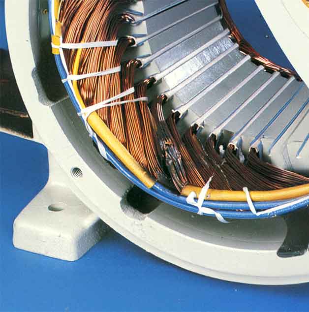
Test Stator and Rotor Windings for Damage
Melted insulation on stator leads (wires #22 and #33 on 16kW models) indicates catastrophic failure. Heat damage typically appears 2 inches back from the stator housing—often caused by lightning surges entering through neutral/ground paths.
Resistance testing protocol:
– Shut down generator and disconnect battery
– Remove T1, T2, and neutral wires from bulkhead connector
– Measure phase-to-phase resistance: Expect 0.4-0.6 ohms at 20°C
– Test each phase to ground: Must exceed 1 megaohm
– Check rotor slip rings: 19-25 ohms indicates healthy exciter field
Replace stator immediately if you find:
– Resistance below 0.3 ohms (phase-to-phase short)
– Ground faults under 1 megaohm
– Visible copper discoloration or carbon tracking
– Rotor resistance outside 15-30 ohm range
Automatic Voltage Regulator Failure Symptoms
A dead AVR kills output even with perfect stator/rotor components. Check for the small LED on the AVR board—if dark during operation, the regulator has failed.
AVR diagnostic sequence:
1. Start generator and let RPM stabilize
2. Locate AVR LED (visible through control panel vents)
3. No LED = power supply failure or dead AVR
4. LED lit but no output = proceed to stator resistance test
5. Measure exciter field voltage: Expect 5-10V DC at 60Hz
Critical replacement notes:
– Match part numbers exactly (printed on AVR label)
– Disconnect battery before swapping units
– Perform voltage calibration per service manual
– Test under 50% load for 30 minutes post-installation
Brush and Slip Ring Maintenance for Older Models
Brushed generators (like 10kW portables) lose output when carbon brushes wear below 3/8 inch or stick in holders. This $18 fix often prevents $3,000 stator replacements.
Inspection process:
– Remove round brush access cover near rear bearing
– Extract brushes and measure remaining carbon length
– Clean slip rings with 600-grit sandpaper using circular motion
– Pro test: Momentarily connect 12V battery across slip rings—should produce >50V AC at outlets
Replacement specifications:
– Use genuine Generac brushes for proper spring tension (2-4 PSI)
– Break in new brushes with 30-minute run at 25% load
– Never operate with brushes shorter than 1/4 inch
Transfer Switch Troubleshooting
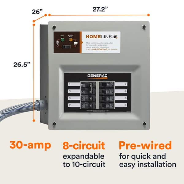
Manual Transfer Verification Procedure
When your Generac generator runs but no electricity reaches the house, the transfer switch often fails to engage. The yellow manual handle position reveals its status: UP = utility power, DOWN = generator.
Safe emergency operation:
1. Turn OFF generator main breaker
2. Insert yellow handle fully into mechanism
3. Rotate handle DOWN to “GEN” position
4. Remove handle immediately—leaving it causes mechanical binding
5. Turn generator breaker back ON
Never operate transfer switch under load except during true emergencies with proper lineman safety protocols.
Electrical Transfer Testing Sequence
Loose coil wires cause 60% of transfer switch failures. Wire #23 (ground signal) from the generator controller must energize the transfer coil.
Coil voltage test:
– Locate 4-wire solenoid coils on transfer switch
– Measure DC voltage during generator operation
– Zero volts = controller or wiring fault
– 12V present but no transfer = mechanical binding
Most frequent failure points:
– Corroded spade connectors on coil terminals
– Lightning-damaged time delay module (older switches)
– Bent manual handle preventing full engagement
– Utility sensing relay welded closed
Power Path Continuity Checks
Neutral and Hot Wire Inspection Protocol
Open neutrals create phantom voltage readings—120V measured to ground but zero under load. This exact scenario caused one homeowner’s 00802-2 model to show 120V at generator but 0V at camper receptacles.
Continuity testing sequence:
1. Shut down all power sources
2. Disconnect neutral at generator junction box
3. Test continuity to transfer switch neutral bar
4. Check L1/L2 conductors end-to-end
5. Critical check: Inspect wire nuts for corrosion (common undersized connection point)
Pro tip: Use lever-nut connectors instead of standard wire nuts—they prevent loosening from generator vibration.
Controller Logic Lockout Reset
Modern generators lock out transfer when detecting unstable frequency or utility feedback. This manifests as correct generator voltage with no load transfer.
Reset procedure:
1. Disconnect 12V battery for 30 seconds
2. Reconnect and start generator
3. Verify stable 60Hz ±0.5Hz operation under load
4. Check utility sensing relay for welding
5. Update controller firmware if available
Prevent Future Failures
Monthly Exercise Protocol That Works
Running your generator unloaded causes residual magnetism loss—the leading cause of “runs but no electricity” failures. Schedule 30-minute runs at 50% load to maintain critical components.
Effective exercise checklist:
– Set automatic exercise for 2AM to avoid noise complaints
– Add space heaters if natural load is insufficient
– Record voltage/frequency readings for trend analysis
– Critical: Test transfer switch operation quarterly
– Inspect for loose connections during runtime
Lightning Protection Strategy
Surges cause 40% of generator electrical failures. Install layered protection:
Non-negotiable components:
– UL-listed surge arrestor at utility service entrance
– Whole-house suppressor at main panel
– Generator-specific surge device at transfer switch
– Isolated 8-foot ground rod bonded to generator frame
Installation must-dos:
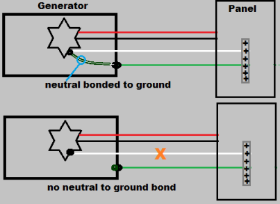
– Use #6 copper minimum for grounding
– Bond neutral to ground ONLY at service entrance
– Replace arrestors after any nearby lightning strike
– Test ground resistance annually (<25 ohms required)
Replacement Part Guide
Stocking $300 in critical spares prevents $3,000 service delays during outages. Match parts to your generator type:
Essential spares by model:
– 16kW air-cooled: AVR ($150-$250), F3 3A breaker, control board fuse
– 10kW portable: Brush set ($15-$25), voltage regulator, starter solenoid
– 22kW liquid-cooled: AVR, governor controller, spark plugs
Smart sourcing tips:
– Order genuine Generac parts for warranty compliance
– Store spares with desiccant in sealed containers
– Label parts with purchase dates (AVRs degrade after 5 years)
– Keep multimeter calibrated for accurate diagnostics
When your Generac generator runs but no electricity appears at outlets, systematic testing isolates the culprit in minutes. Start with breaker verification, confirm voltage at generator terminals, then trace the power path to your transfer switch. Document each test result—this creates a diagnostic trail that prevents repeated failures and accelerates professional repairs if needed. Remember: zero voltage at the generator indicates internal component failure requiring expert service, while voltage present at the generator but absent in your home points to solvable transfer switch or wiring issues. Implement the monthly exercise protocol with load testing, and you’ll avoid 90% of these failures before your next storm hits.


