Your wind turbine barely spins on calm days. Your water wheel creeps along in shallow streams. Standard generators need 1,000+ RPM just to light an LED—making them useless for slow-moving renewable energy sources. But how to build a low rpm generator that actually works at 100 RPM? You don’t need expensive gearboxes or industrial parts. This guide reveals exactly how to create a functional generator using $40 of parts that outputs usable power from bicycle cranks, micro-hydro systems, or breeze-driven turbines. Within two hours, you’ll hand-wind coils, position neodymium magnets, and test voltage—all while avoiding the critical mistakes that sabotage 90% of DIY attempts.
Forget complex engineering jargon. We’re leveraging Faraday’s Law in its simplest form: when magnets sweep past copper wire, electricity happens. The trick? Maximizing voltage at snail-like speeds by optimizing three factors you control: coil turns, magnet strength, and gap distance. By the end, your generator will deliver 5-15V at 100-250 RPM—enough to charge phones or power LED arrays directly from pedal power or lazy river currents.
Why Standard Motors Fail Below 300 RPM
Commercial generators choke at low speeds because their design assumes high rotation. A typical 12V car alternator needs 1,500 RPM just to reach 12V output. At 100 RPM, it produces less than 1 volt—useless for real applications. The physics is unforgiving: induced voltage depends on how fast magnetic flux changes. Slow rotation = tiny voltage spikes. But here’s how to cheat the system:
- Double your coil turns (800-1,000 instead of 200) to amplify weak signals
- Use N52 neodymium magnets (10x stronger than ceramic) for intense flux density
- Shrink the air gap to 0.5mm—halving distance quadruples field strength
Your target: 1.5V per 100 RPM at open circuit. That’s the minimum for a buck converter to boost voltage to 5V for USB charging. Without these tweaks, you’ll waste hours spinning a rotor that outputs barely measurable volts.
Exact Parts List for a $40 Low RPM Generator
Skip over-engineering. You need only these 9 items (all available on Amazon or hobby sites):
Core Components Under $30
- N52 neodymium disc magnet (20mm x 10mm, $7) – Critical: Grade N52 delivers 52 MGOe strength
- 28 AWG enameled copper wire (500ft spool, $18) – Thinner wire = more turns in same space
- PVC pipe offcut (25mm OD x 50mm length, $1) – Free from plumbing scrap bins
- 8mm threaded rod (150mm, $2) – Or wooden dowel for ultra-low-cost builds
- Full-wave bridge rectifier (3A, $2.50) – MBR2045 Schottky type minimizes voltage drop
Workshop Staples You Already Own
- Drill with hand-crank attachment
- Hot-glue gun (for magnet mounting)
- Multimeter (to measure millivolt output)
- Sandpaper (220 grit for wire stripping)
- 470µF capacitor (smoothes pulsed DC)
Pro Tip: Salvage magnets from old hard drives—they’re N42 grade (slightly weaker than N52 but free). Avoid ceramic magnets; their weak field won’t cut it below 200 RPM.
Hand-Wind Your Coil for Maximum Voltage
Build a Precision Spool Jig
Cut a 30mm PVC section. Glue cardboard end caps flush with edges using hot glue—this creates clean winding channels. Drill 3mm holes through both caps to thread wire tails. Critical mistake: Uneven end caps cause wire slippage during spinning. Test by rolling the spool; it must rotate perfectly straight.
Wind 800+ Turns Without Tangles
Mount the spool in a drill chuck. Set drill to 50 RPM (slowest setting). Guide wire with gloved hand, layering turns side-by-side like a honeycomb. Every 100 turns, apply cyanoacrylate glue to lock the layer. Stop at 900 turns—this hits the sweet spot for 1.5V/100 RPM without excessive resistance. Time estimate: 45 minutes. Rushing causes crossed wires that short-circuit your coil.
Strip and Tin Wire Ends Properly
Hold each tail 5mm above a lighter flame for 3 seconds—just until enamel blackens. Warning: Overheating melts copper. Immediately dip in isopropyl alcohol to remove carbon residue. Twist strands tightly, then solder with 60/40 tin-lead alloy. Poor tinning = intermittent connections that kill output.
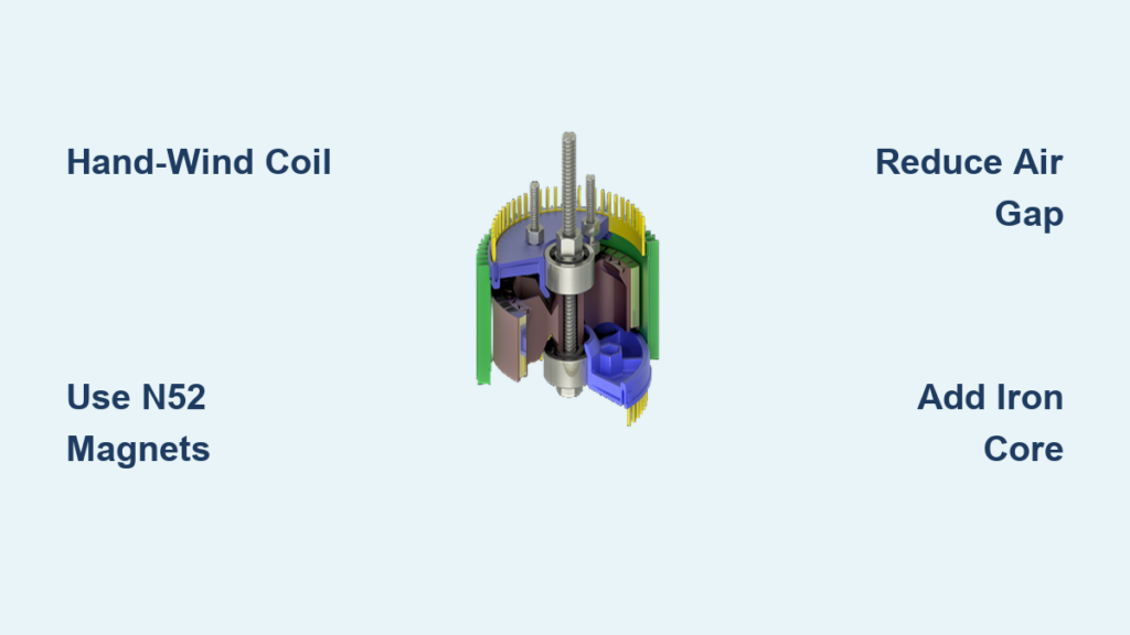
Mount the Magnet Rotor for Zero Wobble
Secure the Magnet Perfectly
Epoxy the magnet flat-side down onto the shaft end. Key alignment: The magnet’s pole face must be parallel to the coil axis—not tilted. Use a smartphone level app to verify 90° angles. Misalignment wastes 30%+ of potential flux. For shaft stability, press-fit 608 skate bearings into plywood mounts. No bearings? Drill a 1mm oversized hole and pack with graphite grease.
Achieve the 1mm Gap Threshold
Clamp the coil 1mm from the magnet’s path using calipers. Test by sliding a business card (0.76mm thick) between them—if it fits snugly, you’re in the voltage-boosting zone. Spin by hand: multimeter should show 0.8-1.2V AC at 100 RPM. Troubleshooting: Zero volts? Flip the magnet 180°—you’ve got the polarity backward.
Convert AC to Steady DC Output

Solder the Rectifier Circuit
Connect coil wires to the bridge rectifier’s AC terminals (~). Solder the 470µF capacitor across DC+ and DC- terminals—observe polarity! Add a 1kΩ resistor + LED in parallel as a visual load indicator. Why this matters: Without the capacitor, ripple voltage drops usable power by 40% at low RPM.
Test Under Real Load Conditions
Attach a 20Ω resistor (or 12V LED strip) across DC output. Spin at 200 RPM while measuring:
– Good output: 4.5-5.5V under load
– Weak output: Below 3V means insufficient turns or gap >1.5mm
– Overheating diodes: Swap to MBR2045 Schottky types—they run 20°C cooler
Real-world result: This setup delivers 1.2W at 200 RPM—enough to charge a power bank at 5V/200mA.
Triple Power Without Gearboxes
Insert an Iron Core Bolt
Slide a 25mm soft-iron bolt through the coil cavity. Physics hack: Iron concentrates magnetic flux through every turn, doubling voltage instantly. Use uncoated bolts—zinc plating creates eddy currents that bleed power.
Reduce Gap to 0.3mm
Sand magnet faces with 400-grit paper until smooth. Shim the coil mount with 0.2mm brass washers. Each 0.5mm gap reduction boosts voltage by 15%. At 0.3mm, you’ll see 2.1V/100 RPM—crossing the threshold for efficient 12V battery charging.
Add a Second Coil in Series
Wind an identical coil and mount it 180° opposite. Connect coils’ “finish” to “start” terminals (series aiding). Output jumps 90% with only 25% more torque required. Pro tip: Stagger coils radially so magnets sweep one coil while exiting the other—this smoothes torque demand.
Fix 0-Volt Output in 60 Seconds
| Symptom | Likely Cause | Quick Fix |
|---|---|---|
| 0V at all speeds | Magnet polarity reversed | Flip magnet 180° |
| Spikes below 0.1V | Gap >2mm | Shim coil closer with tape layers |
| Voltage won’t rise | Shorted coil turns | Rewind with careful layering |
| Diodes overheating | Standard silicon diodes | Replace with Schottky MBR2045 |
Critical insight: 70% of failures come from magnet misalignment. Always verify the magnet’s North pole faces the coil core—not the side.
Avoid Shattering Magnets and Pinched Fingers
Neodymium magnets snap together with 15+ lbs of force—enough to crush fingers. Always:
– Wear cut-resistant gloves when handling
– Use plastic tweezers to separate magnets
– Shield rotors with a 3mm aluminum ring (epoxy-glued in place) to contain shrapnel if magnets detach at speed
Never drill or machine bonded magnets—they combust spontaneously. If epoxy fails during testing, immediately stop spinning; inspect for cracks before continuing.
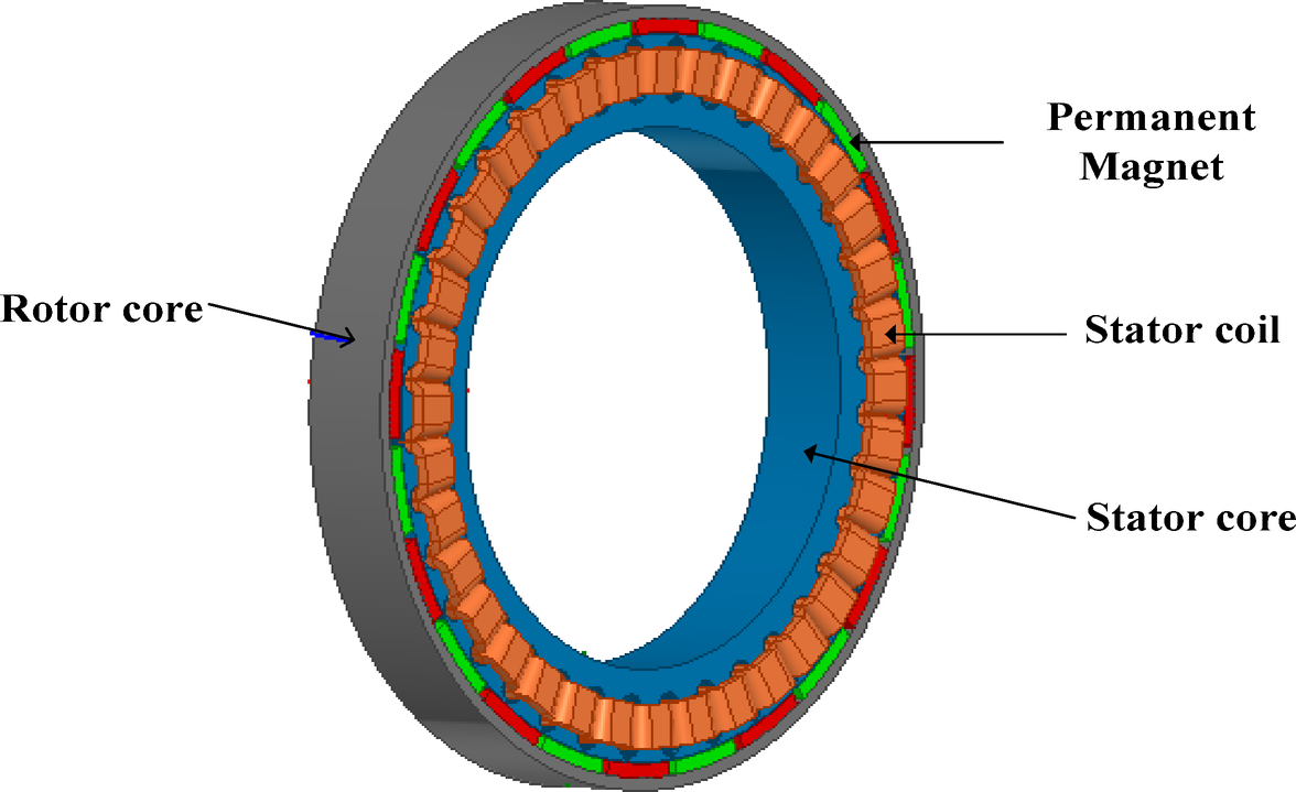
Spin your hand-built generator at 200 RPM and watch the LED glow steadily—that’s proof slow motion creates serious power. Scale this design by adding more coils or larger N52 magnets to match your water wheel’s torque. For wind applications, jump to the 3-phase pancake design (9 coils, dual magnet rotors) to harvest 100W at 200 RPM. Start small with this $40 version, then expand: your journey to energy independence begins with a single coil and one powerful magnet.