Your generator suddenly screams like a jet engine, shaking violently as black smoke billows from the exhaust. The tachometer needle slams past 115% rated speed—this is generator overspeed, a critical failure that can destroy your unit in under 10 seconds. When RPMs exceed safe limits, pistons shatter, bearings melt, and catastrophic engine failure becomes inevitable. This isn’t a minor glitch; overspeed demands immediate action to prevent $20,000+ in repair costs or total generator replacement.
You’ll learn exactly how to stop an overspeed event mid-crisis, diagnose the root cause within 30 minutes, and implement permanent fixes. Whether you’re maintaining a hospital backup system or a construction site generator, these field-tested procedures restore safe operation fast. Skip the guesswork—we cut straight to actionable steps that address the three core failure points: governor malfunctions, fuel system defects, and mechanical damage.
Stop Overspeed Immediately: Life-Saving Shutdown Steps
Emergency Shutdown Within 2 Seconds
Hit the red emergency stop button the moment RPMs exceed 110% rated speed. If the button fails, locate the manual fuel shutoff valve near the injection pump and close it immediately—this cuts fuel in under 3 seconds. Simultaneously disconnect all electrical loads to reduce engine stress; even small loads like emergency lighting can sustain overspeed conditions. Never attempt to throttle down manually, as this wastes critical seconds while components approach explosive failure thresholds.
Critical Safety Protocols After Shutdown
Evacuate all personnel beyond a 50-foot radius immediately. Overspeed generators can eject metal fragments at 500+ mph from failed turbochargers or connecting rods. Wait 30 minutes before approaching—critical components like pistons reach 1,200°F during overspeed events. Before inspection, check for fuel leaks using non-sparking tools; diesel vapors create instant explosion hazards in confined spaces. Document the exact RPM reading at shutdown—this data pinpoints whether the failure originated in the governor (115%+ RPM) or fuel system (130%+ RPM).
Diagnose Governor Failures in Under 30 Minutes
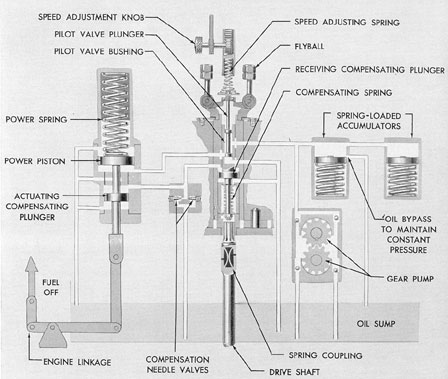
Mechanical Governor Linkage Inspection
Start with the fuel rack position at idle. Disconnect the governor linkage and manually move the rack—if it doesn’t return smoothly to idle position, worn flyweight pins or broken springs are causing uncontrolled fuel delivery. Check for binding in the control shaft using a 0.005-inch feeler gauge; any resistance indicates corrosion or misalignment. Measure spring tension with a calibrated gauge—values below 85% of spec (typically 15-20 lbs) cause sluggish response. Replace all pivot bushings if play exceeds 0.002 inches; this microscopic wear creates delayed fuel cutoff during load rejection.
Electronic Governor Sensor Testing
Test magnetic speed sensors using a multimeter set to AC voltage. At cranking speed (200 RPM), output should read 1.5-2.5V AC; values below 1.0V indicate sensor failure. Verify the air gap with non-magnetic shims—most systems require 0.010-0.020 inches. Clean sensor tips with electrical contact cleaner if readings fluctuate. Pull fault codes via the control panel; codes like “SPN 190 FMI 3” confirm speed signal loss. Replace sensors showing >10% voltage drop across the RPM range—this drift causes dangerous speed miscalculations during critical transitions.
Repair Fuel System Defects Causing Uncontrolled Acceleration
Injector Opening Pressure Calibration
Remove injectors using a proper puller—never hammer them out. Test opening pressure on a calibrated bench tester; diesel injectors must hit 250-350 bar (3,600-5,000 PSI) per manufacturer specs. If pressure is low, disassemble the injector and replace the nozzle spring. Use shims in 0.05mm increments to fine-tune pressure: adding shims increases pressure by 10 bar per 0.1mm. Re-test spray patterns—irregular atomization (like streamers instead of cones) means worn nozzles must be replaced. Document pressures for all cylinders; variations over ±5 bar cause speed hunting that triggers overspeed.
Fuel Pump Delivery Rate Correction
Measure actual fuel output at 50% and 100% load using a flow meter. Compare readings to the pump curve in your service manual—excess delivery (>1% over spec) indicates worn plungers. Disassemble the pump and inspect barrel scoring with a borescope; even 0.001-inch wear increases delivery by 3-5%. Replace metering sleeves if clearance exceeds 0.0008 inches. During reassembly, set plunger preload to exactly 0.005 inches using dial indicators—this critical dimension controls fuel cutoff timing. Verify results with a smoke meter; opacity above 20% at full load confirms improper fuel calibration.
Restore Damaged Mechanical Components

Turbocharger Shaft Play Measurement
Check turbocharger shaft end play with a dial indicator mounted on the compressor housing. Rotate the shaft while measuring axial movement—values over 0.010 inches mean immediate replacement is required. Inspect turbine blades for cracks using a 10x magnifier; even hairline fractures cause imbalance that accelerates overspeed. Before installation, verify oil drain line slope (minimum 15-degree angle) to prevent oil coking. Spin the turbo by hand—it must rotate freely for 5+ revolutions without binding, indicating healthy bearings.
Valve Clearance Adjustment Protocol
Set valves cold using feeler gauges at 0° TDC on compression stroke. Intake valves typically require 0.010-0.014 inches clearance; exhaust valves need 0.014-0.018 inches. Incorrect clearance by just 0.002 inches alters cylinder breathing enough to mimic overspeed symptoms. Roll the engine slowly while checking each valve—sticking valves create uneven firing that confuses electronic governors. Replace rocker arms showing >0.003 inches wear at pivot points; this minute slop disrupts precise valve timing critical for speed stability.
Prevent Future Overspeed With Proactive Measures

Weekly Emergency Shutdown Testing
Simulate overspeed conditions monthly using your load bank. Command a 100% load rejection at full speed—you must see shutdown within 2 seconds at 115% RPM. Test the manual fuel shutoff valve weekly by closing it during no-load operation; it should kill the engine in <5 seconds. Document response times—if shutdown exceeds 2.5 seconds, clean the emergency stop solenoid valves. Verify alarm setpoints annually with calibrated equipment; drift beyond ±0.5% requires immediate control module recalibration.
Monthly Fuel Quality Verification
Test fuel monthly with a portable water detection kit—anything over 200 ppm water content risks injector corrosion that causes sticking. Check viscosity at 40°C; values below 1.9 mm²/s indicate fuel thinning that increases overspeed risk. Install a 2-micron final filter if operating in dusty environments—particulates accelerate injector wear. Most critically, drain fuel water separators daily; accumulated water creates combustion spikes that trick governors into overspeed responses.
Annual Governor Overhaul Checklist
Disassemble mechanical governors annually for critical backup systems. Replace all springs regardless of tension readings—metal fatigue causes sudden failure. Clean governor oil passages with ultrasonic equipment; carbon buildup in 0.005-inch orifices delays response by 300ms. For electronic systems, update firmware to the latest revision—manufacturers regularly patch speed regulation bugs. Rebuild fuel racks every 2,000 hours; worn racks create 5-7% excess fuel delivery at high RPM.
Critical Overspeed Prevention Specs
– Alarm Threshold: 110% rated speed (e.g., 1,650 RPM for 1,500 RPM generator)
– Shutdown Point: 115% rated speed (1,725 RPM)—no exceptions
– Sensor Gap: 0.015″ ±0.002″ for magnetic speed sensors
– Fuel Pressure: Maintain 1.5-2.0 bar above injection pressure at all RPMs
Bottom Line: Generator overspeed destroys units in seconds but is 90% preventable with disciplined maintenance. Start every repair by verifying emergency shutdown function—you can’t fix what you can’t stop. Prioritize governor linkage checks over electronic diagnostics for 80% of field failures. Document every fuel pressure test and valve adjustment—these records reveal creeping wear before catastrophic failure. Most importantly, never skip weekly emergency stop tests; that 5-minute procedure saves millions in avoided downtime. Your generator’s reliability hinges on treating overspeed prevention as non-negotiable, not optional maintenance.


