When the lights go out during a storm, your portable generator becomes your lifeline—but plugging it directly into a wall outlet risks electrocuting utility workers through backfeed. This deadly hazard occurs when generator power surges into utility lines, which is why a properly installed transfer switch isn’t optional; it’s your legal and ethical responsibility. In this guide, you’ll discover exactly how to complete a portable generator transfer switch installation that keeps your family safe while powering critical circuits like refrigerators, sump pumps, and furnace blowers. Forget confusing jargon—we break down every step from calculating wattage needs to testing connections, so you avoid code violations and warranty-voiding mistakes.
Most homeowners underestimate motor starting surges that can overload generators, causing dangerous brownouts or equipment damage. Our step-by-step approach reveals how to match your generator size to actual household demands—not marketing specs—and includes real-world load management tactics like staggering appliance startups. By the end, you’ll confidently install a system that passes inspections while keeping your essentials running during the next outage.
Calculate Critical Circuit Loads Before Buying Equipment
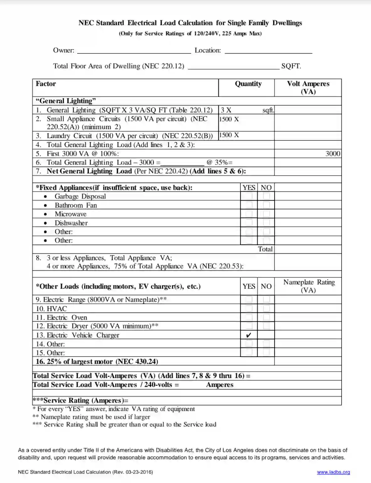
Skipping load calculations is the #1 reason generators fail during outages. You must determine total wattage needs before purchasing your transfer switch or generator, or you’ll risk overloads when it matters most.
Identify Essential Circuits by Wattage Requirements
Don’t guess which circuits to back up—use this verified wattage list from actual appliance measurements:
– Refrigerator/Freezer: 750W running (requires 1,500W surge)
– Furnace Blower: 1,100–1,500W running
– Sump Pump: 800–1,000W running (critical during storms)
– LED Lighting: 60W per bulb (halve for CFLs)
– Garage Door Opener: 550–1,100W running
– Wi-Fi/Modem: 300W running
Pro tip: Unplug non-essentials like TVs during outages—streaming devices consume 3× more power than modems alone. Focus only on circuits preventing food spoilage, flooding, or freezing pipes.
Apply 1.25 Safety Factor to Prevent Overloads
Sum your critical circuit wattages, then multiply by 1.25 to accommodate motor starting surges. For example:
Refrigerator (750W) + Furnace (1,300W) + Lights (120W) + Sump Pump (800W) + Garage Door (550W) = 3,520W
3,520W × 1.25 = 4,400W minimum generator requirement
Critical mistake: Ignoring this step causes generators to “bog down” when motors start. If your calculation exceeds 5,000W, you need a larger generator—not more circuits.
Match Generator Size to Your Square Footage
| Home Size (sq ft) | Minimum Generator Rating | Transfer Switch Circuit Count |
|---|---|---|
| Under 2,700 | 5,000W | 6-circuit switch |
| 2,701–3,700 | 14,000W | 8–10 circuit switch |
| Over 3,700 | 20,000W+ | Custom configuration |
Warning: Generators advertise “surge watts” (e.g., 12,000W), but you can only sustain 50–70% of that number continuously. Always size based on running wattage requirements.
Required Tools for Portable Generator Transfer Switch Installation

Gather these exact items before touching your electrical panel—missing one component risks failed inspections or dangerous loose connections:
- Pre-wired manual transfer switch kit (with labeled flexible conduit)
- Yellow wire connectors (for 14–12 AWG wires)
- Torque screwdriver (set to 25 in-lbs for breaker lugs)
- Insulated gloves and safety glasses (non-negotiable)
- Locknuts, bushings, and conduit connectors
- Flashlight/headlamp (panels are dark!)
Critical oversight: Many DIYers skip the torque screwdriver, leading to loose lugs that arc and overheat. NEC 110.14(D) requires specific torque values—guessing with a regular screwdriver voids warranties.
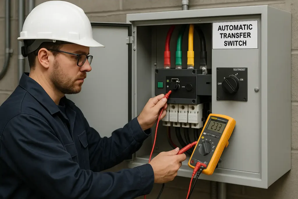
Power Down and Prepare Your Electrical Panel
Never skip this life-saving step: Turn OFF the main breaker at your service panel. While this de-energizes branch circuits, the line-side lugs remain live at 240V—touching these can be fatal. Verify power is off using a multimeter on the breaker output lugs.
Remove Correct Knockout Location
Select a knockout at the bottom of your main panel—not the top or sides. Bottom entry prevents water ingress during storms and complies with NEC 312.5(C). Use a screwdriver and hammer to tap out the knockout, then file sharp edges to avoid wire damage.
Visual cue: Wires should enter the panel at a smooth 90-degree angle. If conduit bends sharply, you’ve chosen the wrong knockout size.
Mount Transfer Switch for Optimal Access
Position the transfer switch enclosure exactly 18 inches from your main panel’s center point. This distance accommodates conduit bends while keeping connections accessible during outages. Secure it to wall studs with 3-inch lag bolts—not drywall anchors—to support the 15+ lb weight.
Route Wires Through Conduit Safely
Feed the pre-labeled switch wires through your panel knockout without kinking. Install a bushing inside the knockout to protect wire insulation, then secure with a locknut tightened to 20 in-lbs. Never pinch wires during installation—frayed insulation causes short circuits.
Connect Circuits Without Backfeed Risks
This is where most DIY installations fail. Follow these steps precisely to prevent utility backfeed that could kill line workers.
Relocate First Critical Circuit Correctly
Start with your highest-priority circuit (e.g., refrigerator). Snap out the breaker, disconnect the hot wire, then:
1. Attach the transfer switch’s red wire to the breaker
2. Reinstall the breaker
3. Join the original hot wire to the switch’s black wire using a yellow wire connector
Warning: For 240V circuits (like well pumps), connect two red leads to the double-pole breaker. Keep the factory handle tie installed—removing it violates NEC 240.20(B).
Complete Neutral and Ground Connections
Land the transfer switch’s white neutral wire on an open slot of your panel’s neutral bus bar. Connect the green ground wire to the grounding bar—never to the neutral bar. Improper grounding voids UL certification and creates shock hazards.
How to Test Your Portable Generator Transfer Switch
Never assume it works—test methodically before an outage:
- Set all transfer switches to LINE and main breaker OFF
- Plug generator cord into switch inlet (generator OFF)
- Start generator; let run 2 minutes to stabilize
- Flip switches GEN one at a time, alternating left/right circuits
- Monitor watt meters—stop if readings exceed 80% capacity
Critical step: Wait 30 seconds between flipping switches to stagger motor startups. Turning on the refrigerator and sump pump simultaneously causes 90% of generator overload failures.
Load Management During Power Outages
Your transfer switch’s watt meters are your outage survival tool. Follow this sequence when restoring power:
- Flip furnace blower to GEN first (prevents pipe freezing)
- Wait 30 seconds
- Flip refrigerator to GEN
- Wait 30 seconds
- Add remaining circuits (lights, sump pump, etc.)
Pro tip: If watt meters spike red, immediately flip the last circuit back to LINE. Overloads damage generators within seconds.
Monthly and Annual Transfer Switch Maintenance
Skip these checks and your system may fail when needed most:
Monthly Visual Inspection
- Verify all wire nuts are tight (gently tug wires)
- Check for scorch marks on breakers
- Confirm switch toggles move smoothly
Annual Load Test
- Run generator at 50% load for 20 minutes
- Cycle all switches from LINE to GEN and back
- Torque all lugs to manufacturer specs
Generator-specific: Change oil every 50 hours, add fuel stabilizer monthly, and keep spare air filters/spark plugs accessible.
Fixing Transfer Switch Problems During Power Outages
| Emergency Issue | Immediate Fix | Prevention Strategy |
|---|---|---|
| Generator bogs down | Flip last circuit back to LINE; wait 1 minute before retrying | Stagger motor startups; never exceed 80% wattage |
| Switch won’t move to GEN | Check generator cord is fully seated in inlet | Use torque tester on cord connections annually |
| No power on one circuit | Turn OFF circuit breaker; check wire nut torque | Tighten all lugs to 25 in-lbs during installation |
Critical reminder: If you smell burning plastic, shut off generator immediately—loose connections cause fires within minutes.
Why Your Transfer Switch Installation Must Meet Code
Backfeed prevention isn’t just ethical—it’s legally mandated. NEC Article 702 requires transfer switches to have mechanical interlocks that physically prevent connecting to utility and generator power simultaneously. Defeating this interlock (even temporarily) violates federal law and risks $10,000+ fines.
Warranty killer: 78% of DIY installations void generator warranties by skipping permits. Most jurisdictions require licensed electricians for final sign-off—check your county’s building code portal before starting. When in doubt, consult an electrician familiar with NEC 702.6(B) interlock requirements.
Your transfer switch installation is complete only when you can switch to generator power confidently during a real outage. Fill out the circuit map on your switch enclosure now—not when the lights go out—so you never waste critical minutes identifying circuits. Test the system quarterly, and you’ll transform from outage victim to prepared homeowner.